S1 Exige Conversion

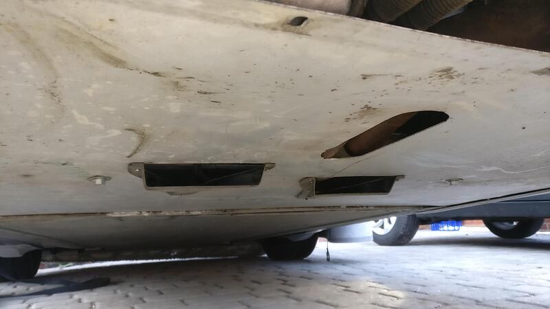
Very good. I have not read this is detail but it looks like you have the panel with the NACA ducts the wrong way up. The plastic “scoop” should be on top, into the engine bay. At least that’s what my memory tells me and it’s too cold to go and check. It would be a shame to fettle everything for a perfect fit and then find it does not fit the other way up. Keep up the good work.

Oh, I don’t think the chassis numbers sequences matches the build sequence. I had never noticed the optional fixings.

This panel is definitely upside down:

:open_mouth:

Oops, ahh well it gave the position of the diffuser and is off the car again so no harm done. I’ll have to take better care when putting everything back together.

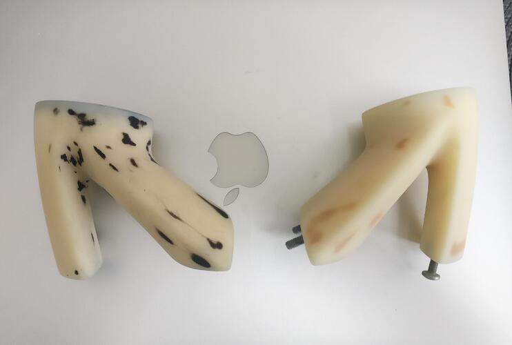
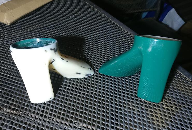
I didn’t know what to do with the spare wing mirror pieces not going on the car so decided to keep as much as I could for spares.

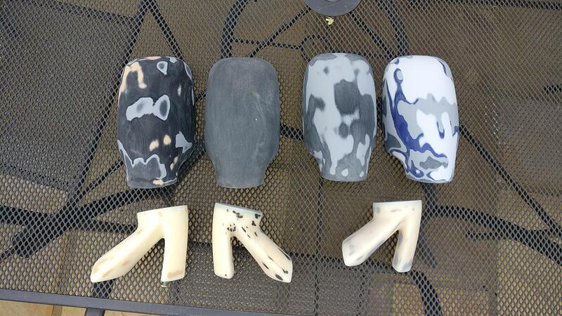
Really boring to sand as they’re fiddly and hard to get up into the grooves, but took the plinths mostly back to the plastic.

I decided to sand as many pieces as I can (hopefully will get the plinth that is stuck on the car off in one piece but I’m not very optimistic) and will spray them all and choose the best looking to go on the car.

I think everything had been painted differently over the years as some were taken back to the bare plastic pretty easily, others had thicker primers and every primer was a different colour, even on pieces that were the same base coat colour.
I added a bit of filler on one cover due to some nasty stone chips but they’re all ready for primer.

I almost didn’t bother posting this as it was pretty pointless, but I’ve always hated the immobiliser on my car. I had my first immobiliser go into meltdown and left me stranded and because of this I don’t trust them. I’ve always wanted my car to be as simple as a turn of the key like my first S1, one less thing to go tits up!
With this in mind I thought I’d take a punt on an immobiliser bypass plug.

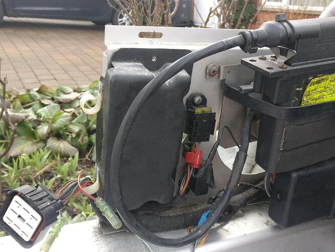
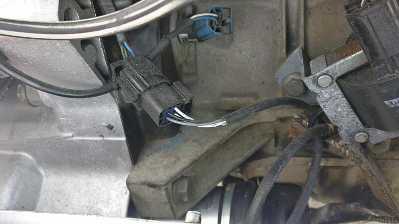
I am pretty sure I’m currently running the Rover system, but had no idea what I would find inside the plastic cover. With the clam off it is much easier to access so decided to investigate.

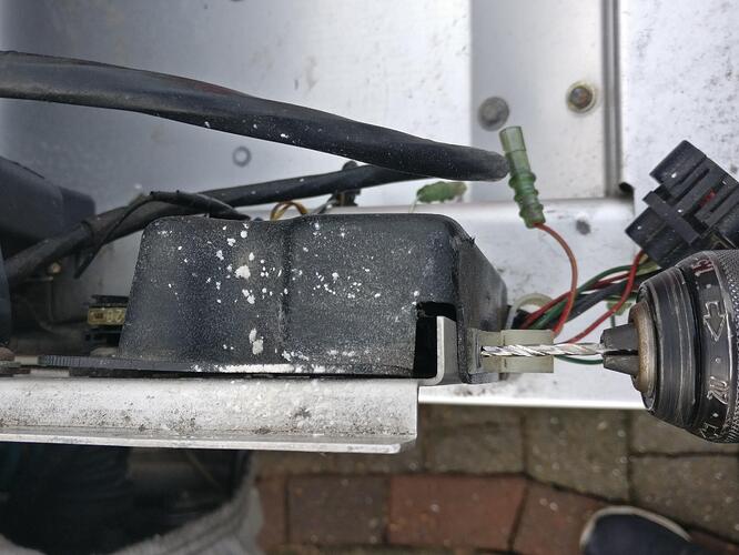
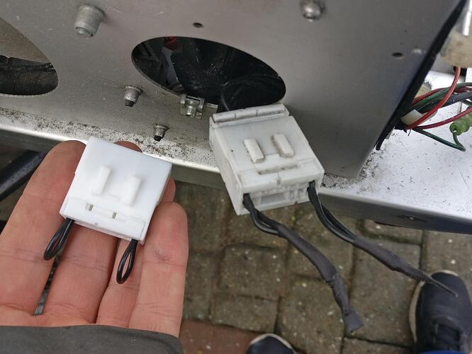
To fully remove the cover you have to drill out the pop rivets. Thankfully I was able to grab what was inside and pull it out through the hole in the back.

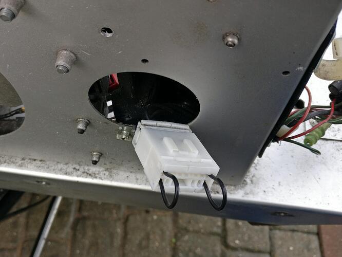
Turns out the set up was identical to what I bought, a plug that had the wires blanked off.

I decided to swap it out anyway and test it. Nothing happened and I still had to use my key fob to start that car, so seems it only bypasses the Cobra systems but not the Rover one. Looks like I’ll have to put up with the immobiliser for a bit longer and have no idea how the Rover system is completely turned off, but might be something I look for in the future.

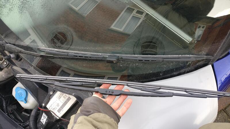
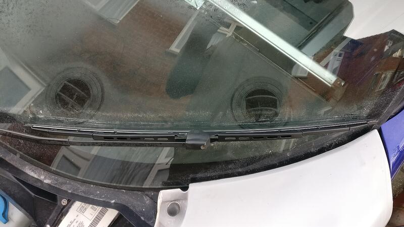
Another boring post but decided to replace the rather worn out wiper blade. No idea if it has ever been changed but for £7 why not.

I decided to replace with the same size as the current one at 24". Apparently 26" would fit too but I didn’t want the blade to go any further over the Lotus sport sticker on the sun visor than it already does.

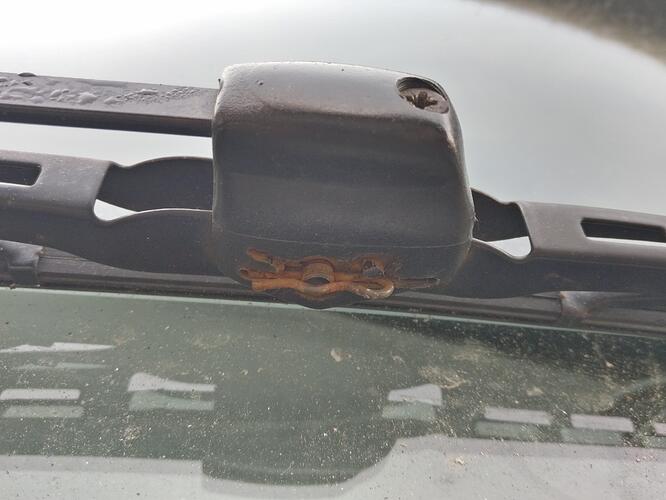
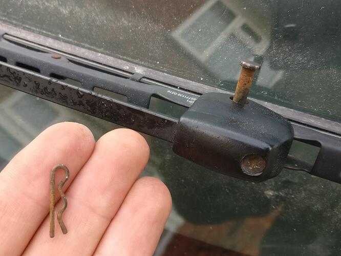
Really simple to fit, first is to remove the split pin.

With the pin out the centre pin slides out.

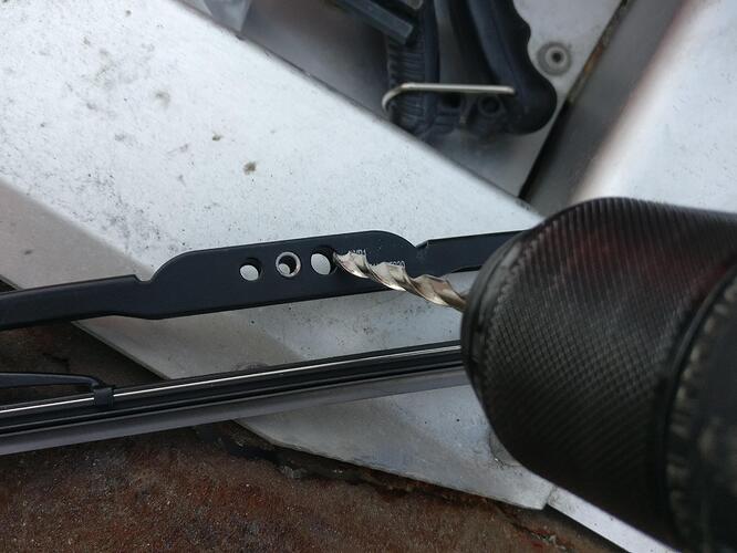
I could have used the other fixing hole, but I wanted to keep the same position so drilled the middle out to 5mm to allow the pin to go through.

I popped both pins back through and job was done. Will see if it does better when I can actually drive the thing.

I would get shot of those chock connectors in the wires, they are the work of the devil and invite problems. If I have to splice into a wire (as I did for my shift lights) I do the following.

Melt a small collar of insulation off the wire you are joining to with a soldering iron.
Solder the joining wire onto the exposed part.
Secure with a good quality insulation tape (the stretchy waterproof sort).
Perfect electrical connection, cheaper and lighter as well!

Could you please post the manufacturer and the reference number of the wiper blade
you did install.

Thank you

Got a sale on so should bring the price down a bit

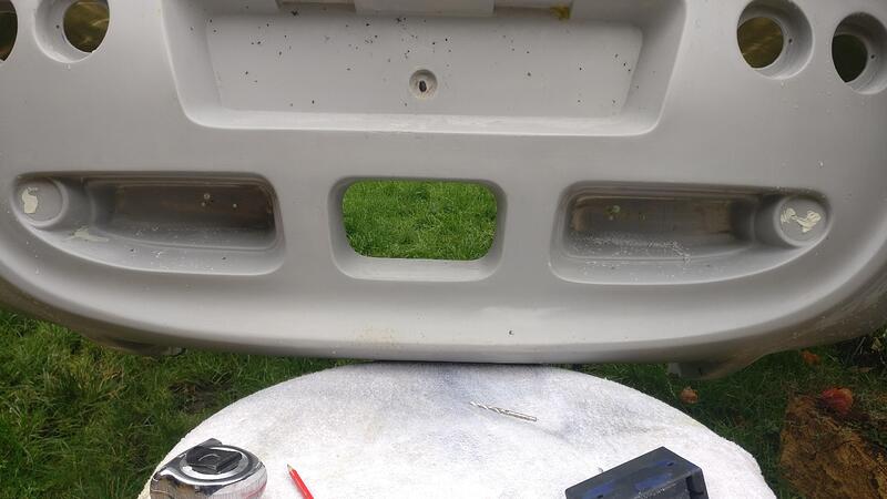
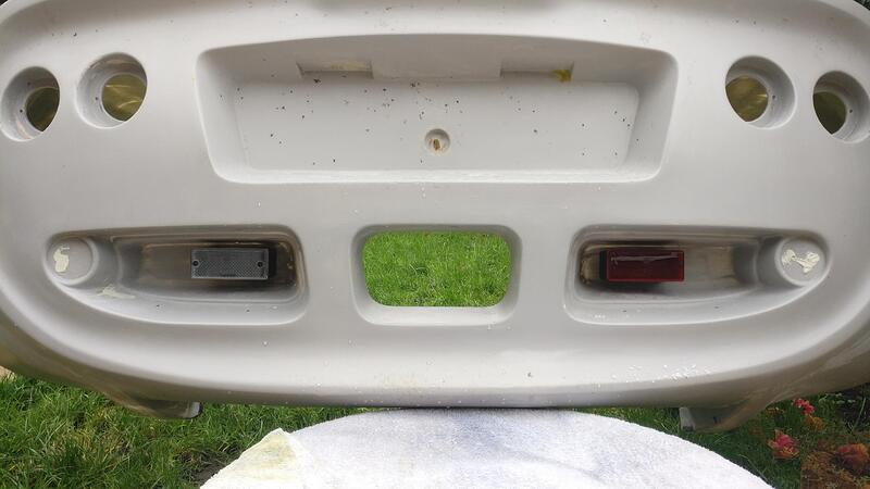
Struggled to get the rear clam into the rear garden (had to take the side gate door off) but it is much easier to cut all the holes I need with it off the car and get it ready for the body shop.

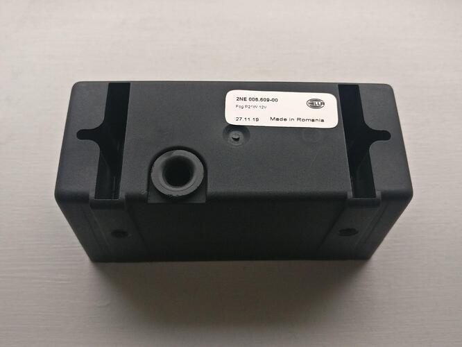
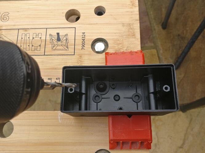
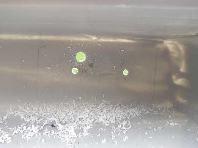
On my new fog and reverse light housings I needed to drill the holes for mounting.

On the inside the moulding has a guide which is handy and made it easy to drill straight through.

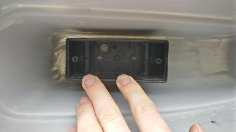
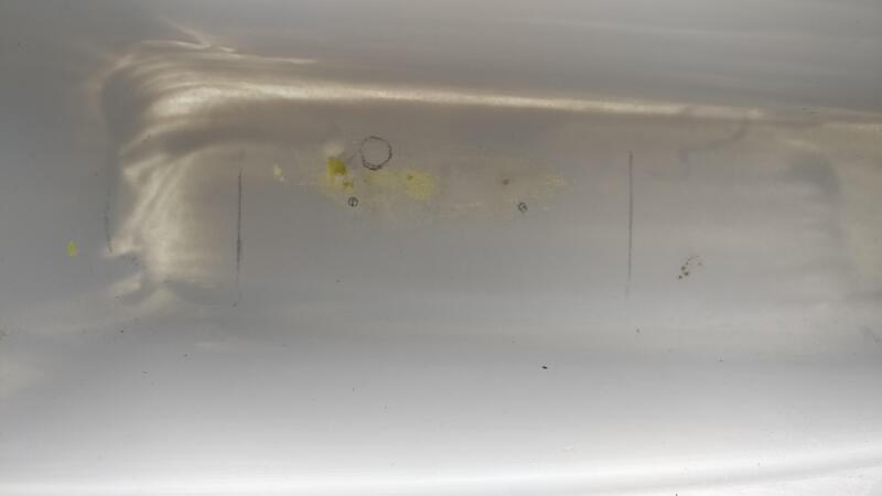
Rather than making a template I was just going to find the position by eye and a tape measure. I held the housing in place and marked the edges and where to drill. I then used the tape measure for one of the edge lines and did the same on the other side to ensure they matched.

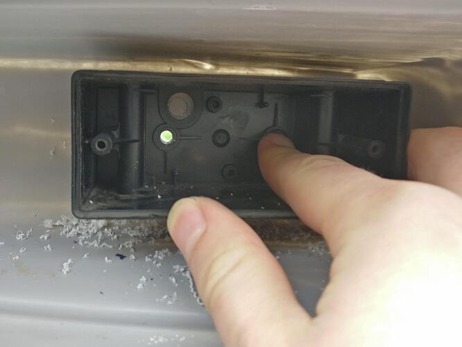
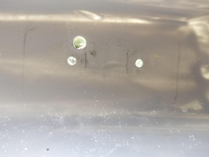
After drilling the first hole I then popped a screw through and held the housing in place to drill the other 2, using the housing as a guide, ensuring everything would line up.

The hole for the wires will need to be opened up a little to get the connectors through, but I need to grab the loom to test how small I can get away with. The connectors are square so I won’t open the circle up any more but I’ll make it more rectangular instead, that way the hole is more likely to stay covered by the light.

Duplicated both sides.

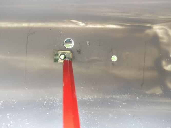
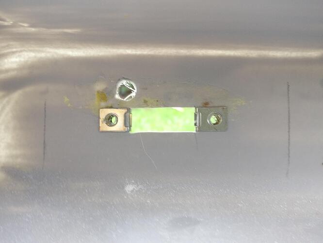
I forgot to take off the spire nuts from my Elise clam when I sold it, so I bought some new M4 nuts. I held them in place so I could see right through the hole, then marked where I’d need to open the hole up to.

Not the neatest hole but it won’t be on show and the nuts fit very well. You could just put a normal nut on the end of the bolt and skip this step of opening up this rectangular hole. However it would be very difficult to get to that nut when the clam is on if you want to remove the light for whatever reason. With this in mind I decided to go the extra step to allow me to remove the light with the clam on the car.

Very happy with the position of both lights, I didn’t check which way round the lights go (I think this is right) but I did make sure the writing on the lenses were the correct way up!

Very nice job.
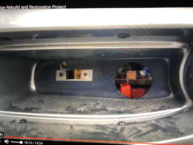
To complete the job you will need the two stickers that cover the recess’ bottom.
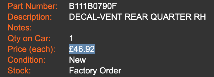
RH B111B0790F
LH B111B0789F

There would be, as far as I know, also a variant with a lateral hole in the recess to
let the air evacuate.

Have a nice day

P.s.: If you don’ t find the stickers I will soon have some replicas made. :thumbup:

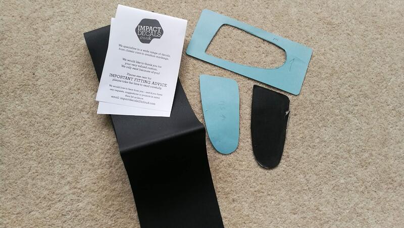
You can make your own from stonechip vinyl, I did the front ones on mine a while back, got the stuff from these guys via eBay: :thumbup:

Edit: Jesus, I’ve just seen the price Lotus want for stickers :crazy: :lolno:

I’m going to leave the fog/reverse light areas clean of vinyls and won’t be cutting any holes, but all personal preference.

I also have bought a sheet of stone chip to make my own front intake vinyls, not only to save money but also because I’ve never seen an Exige with vinyls that fit well (in my opinion), which is extremely noticeable on lighter cars. I bought enough so that if I did change my mind about the fog/reverse light bits needing the vinyl I have it ready to go.

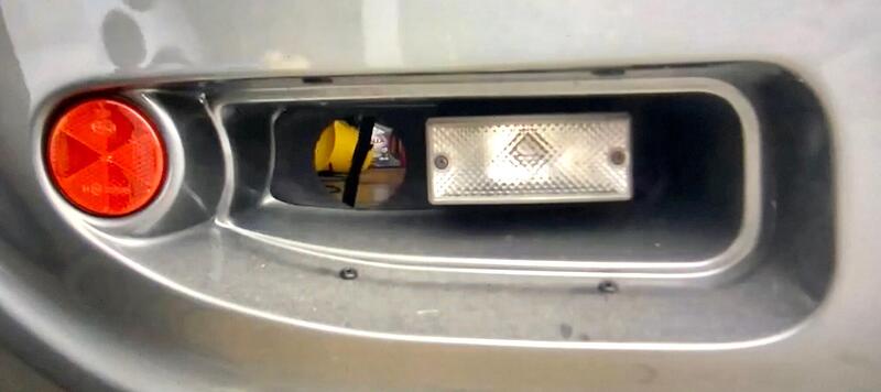
Not the best images but you get the idea that the stickers are smaller than perhaps they should be leaving gaps around the edges.

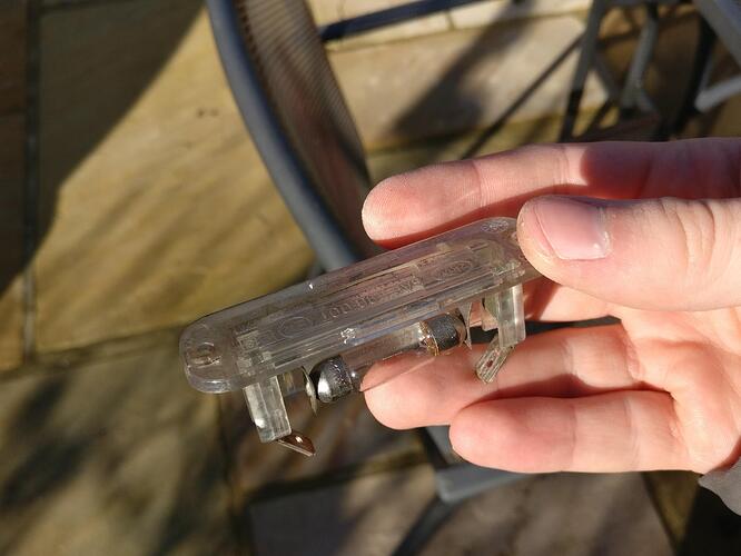
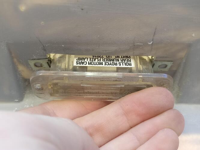
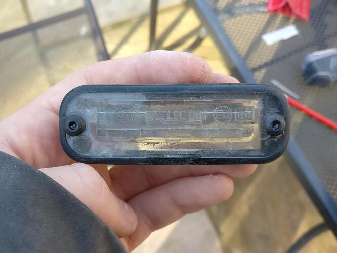
Numberplate lights were sorted through a near identical method to the fog/reverse lights, with a few tweaks here and there.

I’m reusing my current ones but will clean them up a bit.

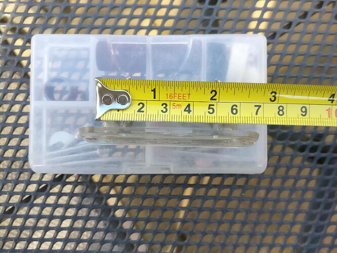
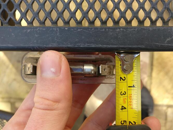
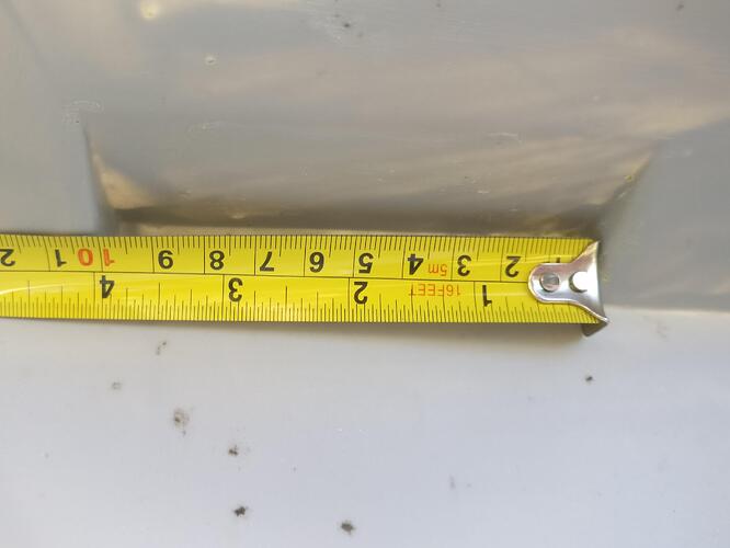
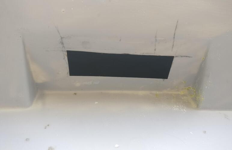
Unlike the fog/reverse lights where you could get away with just drilling 2 fixing holes, as the numberplate light housings go up into the clam the larger holes needed to be cut. I measured the length of the inner housing and the width. 60x17mm was needed but I’d allow a touch more tolerance as the rubber edging should cover everything if the hole is a little bigger than needed.

I needed to find the centre of the recess so got the tape measure. 100mm so found the half way mark and measured 30mm either side of it.
I guessed a bit with how far away from the numberplate face the light would sit and decided on 30mm for the furthest edge of the hole from the vertical face.

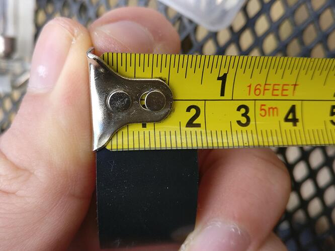
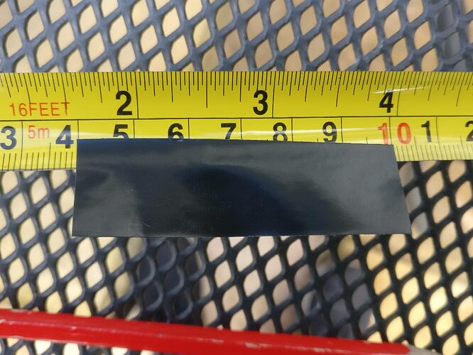
I then found that a roll of electrical tape is 18mm, perfect size to give me my tolerance.

I measured out a 60mm length and I had my template for the required hole.

Template in place and much easier to follow than just pencil lines.

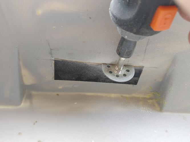
I used a combination of disc and drill bits on my dremel to cut the shape of the tape. I went a little off-piste with the cutting as it was hard to see cutting with your head upside down, but no harm done and the other side was neater.

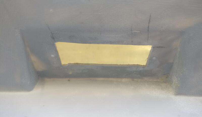
Not the prettiest hole and still a touch too small so I took some files and opened and cleaned it up.

I opened and smoothed the hole a little and now the light sits nicely with no nasty tension on it. You can also see 2 small indents into the clam either side of the hole which mark the position of the fixing bolts. These were made by carefully using a drill bit through the housing fixing holes like how I drilled the fog/reverse lights. Once the marks were made I removed the housing and continued through the clam so not to damage anything as it is almost impossible to get any drill or dremel perpendicular to the surface.

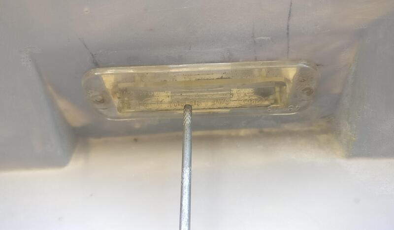
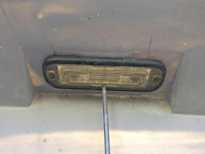
A quick test fit and even without the rubber edging no gaps or holes were showing.

I originally planned to use the same M4 spire nuts as on the fog/reverse lights for the numberplate lights, but the tolerances didn’t match as the holes for the numberplate light are too close to the main housing. I will either just use a simple nut and washer or cut the spire nut in half and bond it to the underside of the clam so the light is easily removed with the clam on.

I popped the rubber edge on and realised how dirty they were and placed the new M4 button head holts through. Much better looking than the Phillips head screws used previously.

Another test fit and very happy with the outcome, just need to try and bond/glue the spire nut (I suppose now more like a captive nut) to the inside.

Filled the gearbox back up using the stored fluid from the driveshaft swap.

I decided to refill through the conventional method and cracked loose the refill plug

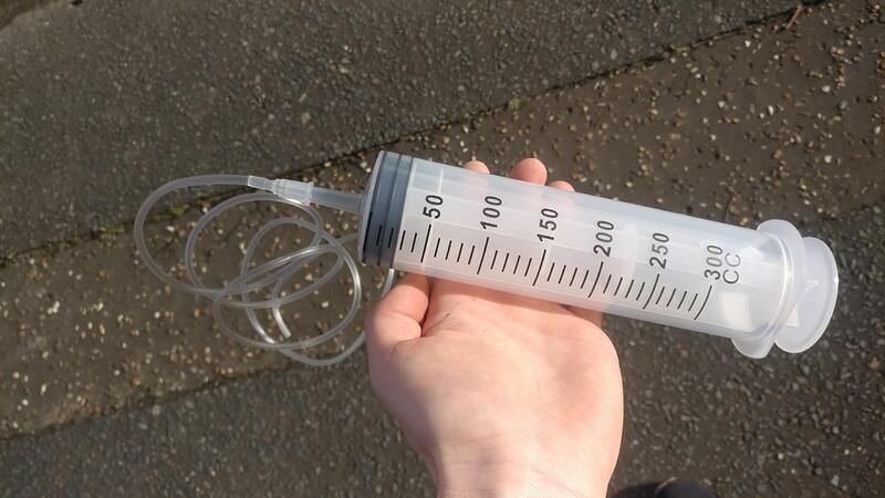
I bought a 300ml syringe to pump it back in. I would say I wish I had a larger gauge pipe as it took a while and a fair amount of pressure to get the thick oil back in.

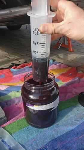
Nice and easy to suck up with minimal mess and waste.

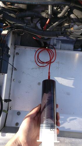
Tucked the pipe into the refill hole and began squeezing. Took about 7 pumps I think to refill.

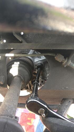
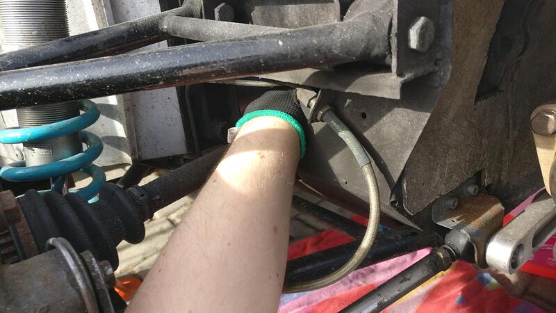
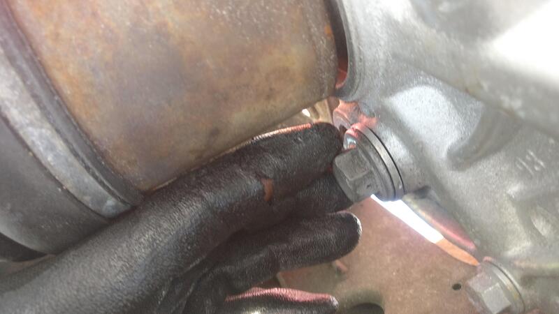
I managed to squeeze my hand through the subframe and tightened the refill plug up.

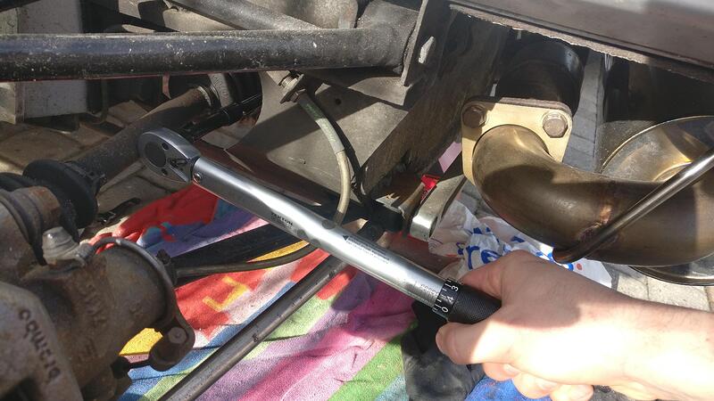
I then took a long extension and torqued the plug up to 45nm.

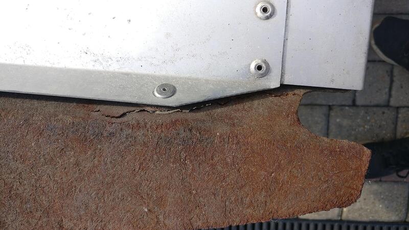
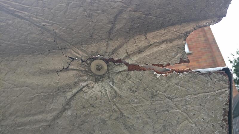
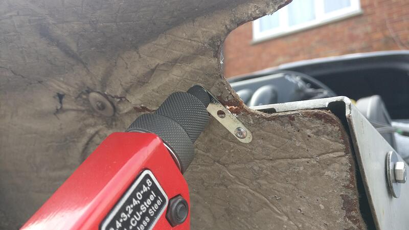
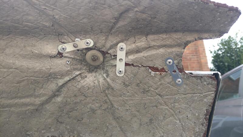
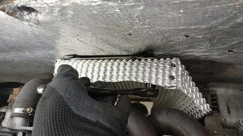
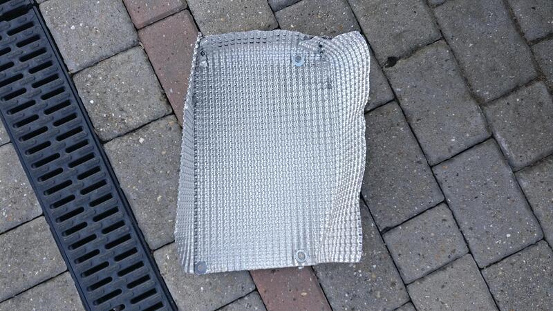
A downside of having the rear clam off and a car cover is that after a windy night the brittle heat shield connected to the boot floor has cracked and split.

It won’t be problem when the clam is on but to help strengthen and secure it I decided to brace it.

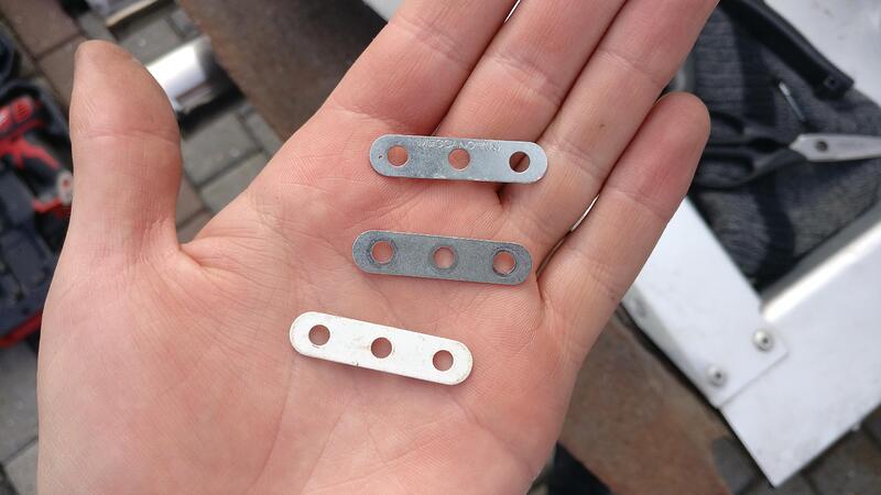
I found some Meccano strips that would be perfect to brace it and pop rivet on.

I drilled a few holes where I thought would be the best to strengthen the crack and pop riveted the strips on.

Hopefully these will secure and stop the split from growing, at least until the clam is back on.

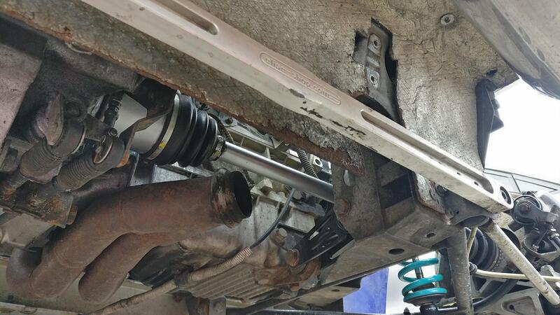
I will start off by saying DO NOT try and short cut this job. As you’ll see I went all around the houses just to end up doing what I wanted to avoid.

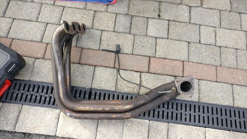
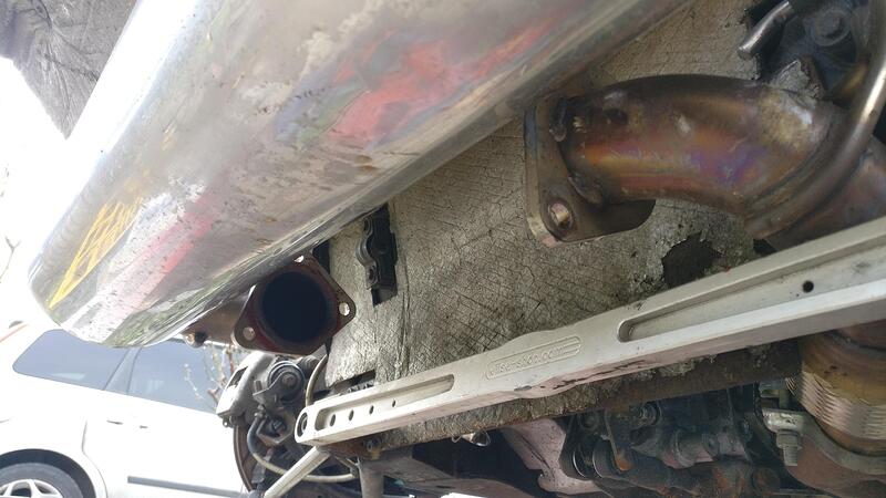
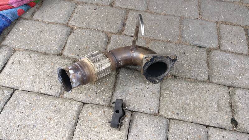
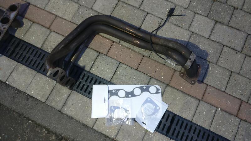
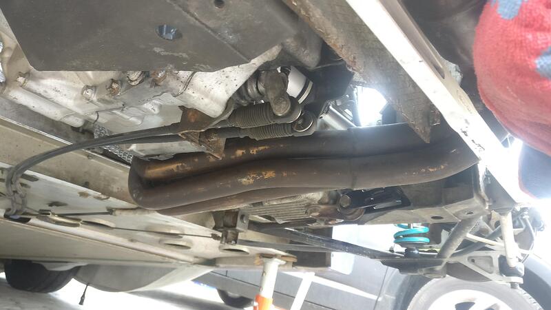
I sourced a solid small bore manifold and think it’ll be a much better fit for my engine set up than the large bore Janspeed flexi I have currently. I believe it is an EBD manifold going by the fixing bracket by the cat end, which Dave Andrews highly recommends on his website. Although my head is a Vulcan head (near identical to a VHPD) as far as I’m aware it hasn’t had any additional porting, so the large bore is probably not the best option. The small bore should match the port size much better and the longer pipe sections replacing the flexi section should improve torque a little bit.

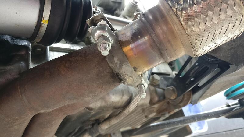
First step was to remove the sports cat. Pretty much a decat pipe with a bit of baffling in the middle.

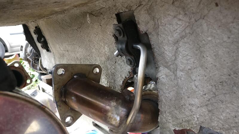
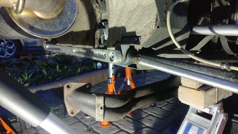
Next step was to remove the flexi section. Nice and easy with just 2 nuts to undo and it slide through the hole and away.

Although it fit through the gap between the heat shield and brace bar, I would have to remove one of the fixings on the brace bar to allow the solid one to fit before bolting it back.

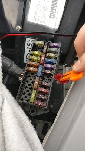
To save the fuse blowing in the alternator I found the fuse and removed it. As a bit of extra protection I also disconnected the battery.

Before I went too far I tested to see if any of the manifold nuts would be a pain. Thankfully as they were recently put on when the Janspeed went on they all came loose fine and left the bolts in the head.

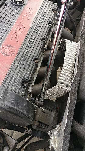
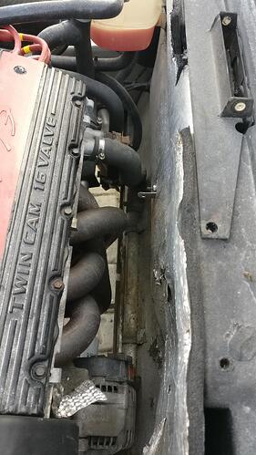
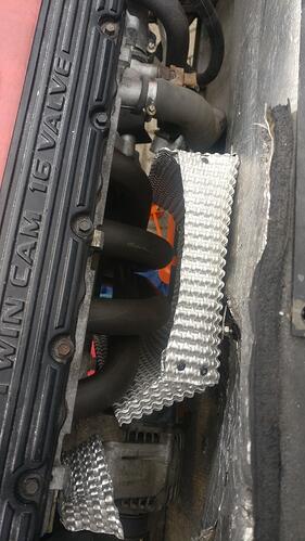
Next up was to remove the nimbus heat shield. His was new on when the Janspeed went on and fixed up 4 bolts, 2 at the top and two at the bottom, which were only accessable from under the car.

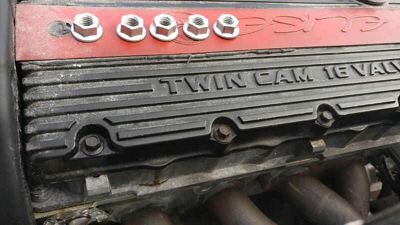
With the heat shield out the way I took the 5 manifold bolts off and put them somewhere safe.

I then unplugged the lambda sensor. The new manifold had a sensor with it that was pretty new so not going to bother swapping them over.

I removed a couple of bolts for the throttle cable and moved it to the side to get a bit more clearance.

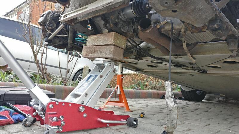
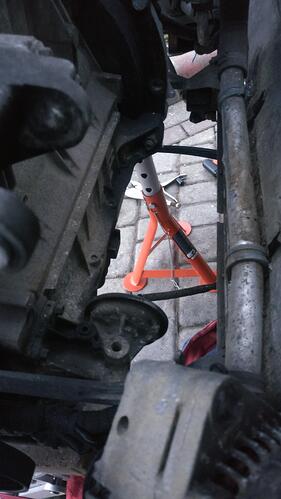
I was hoping to avoid taking the engine mounts off, but I just couldn’t get the clearance. I started with the lower engine stay bolt which let me rock the engine back and forth a bit, but it wasn’t enough.

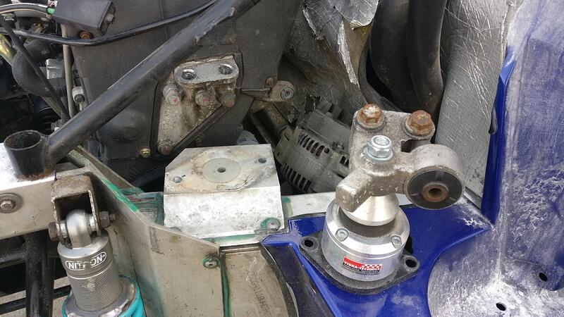
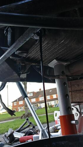
I supported the engine underneath while I undone the RH side engine mount. This allowed me to pull the engine back a bit, but still not enough to give me clearance. I also removed the alternator in a failed attempt to get the required clearance.

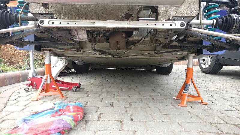
In the end I decided the only way I was getting the manifold out was to remove the oil filter. I don’t have any oil here at the moment so wanted to avoid this, especially as the oil in there is less than 300 miles old. I placed a bucket underneath and removed the bleed bolt on the sump. Once that was drained I removed the oil filter and let the remaining oil in the drain out.
All this fuss could have been avoided if I’d just made the decision to remove the oil filter. I honestly don’t know how you’d get the manifold out without removing it. Don’t do what I do and try to take short cuts because it won’t work here, or certainly I couldn’t make it work.

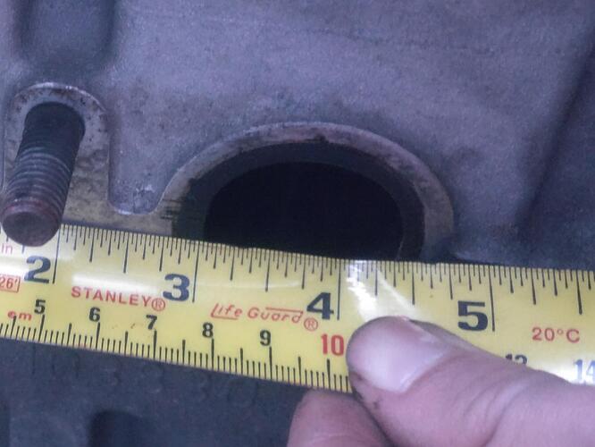
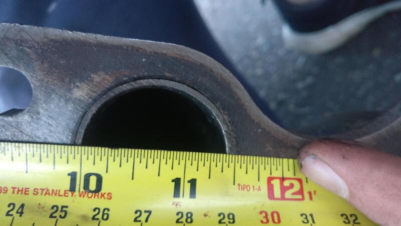
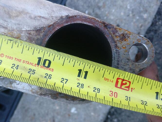
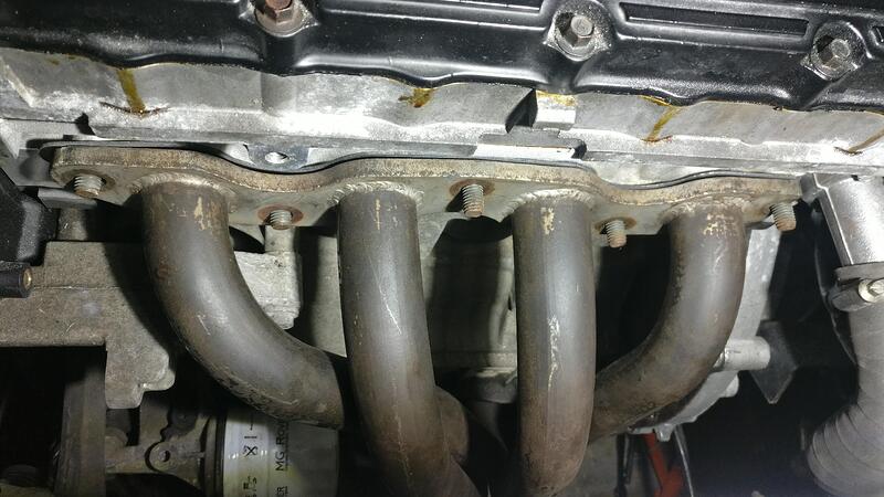
With the manifold off I was able to measure the size of the exhaust ports. Being a metric person I don’t really know inches, but I believe that’s how exhausts are measured.

What I was happy to learn was that the new manifold would match the exhaust port so there would be no nasty step either too small or large.

The Janspeed manifold may have been better if the exhaust was ported more, but I’m confident that I’ve made the right choice for this engine and head.

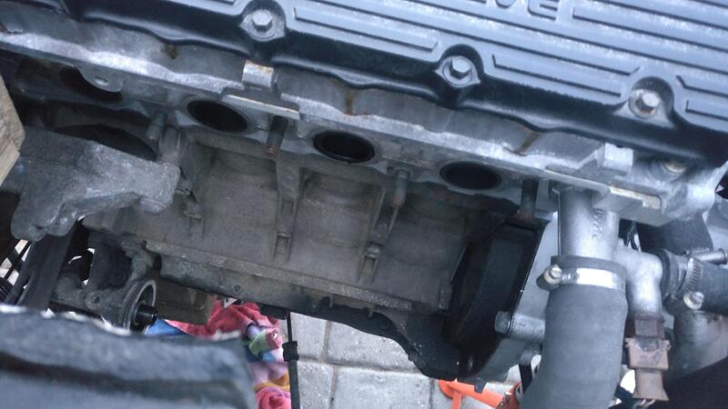
Here’s the hole I would have to fill with the new manifold.

I got all new gaskets ready to put everything back together.

I got the new manifold most the way, but had to drop one side of the brace bar down to allow the manifold up into the gap.

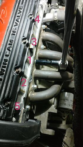
I got the manifold onto the studs but couldn’t get it sitting flush on its own, so I had to use the nuts to pull it against the gasket.

I torqued them down to 45nm in the order shown.

I popped the heat shield back on along with all the other bits and bobs I removed to get the proper position on the manifold for the next step.

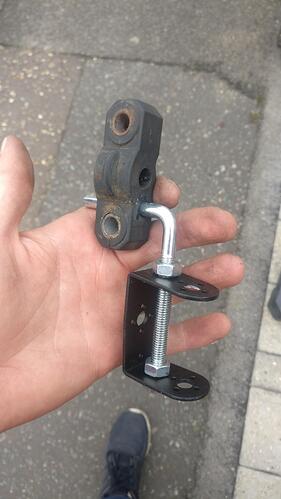
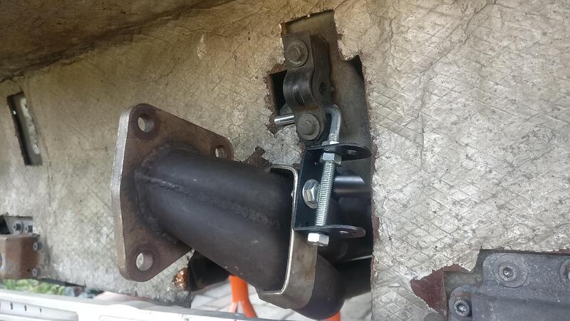
The manifold didn’t come with a fixing for the back section, so I had to make one. It is very DIY and bodge but I am hoping it will do the job. It would give me some adjustment room if needed. I had to drill the rubber mount lower because of the length and the gauge of the L piece.

I mounted the rubber to establish where to drill the mounting holes on the exhaust. I finished it with loctite on the threads to help secure everything. I’ll have to see if it actually works and is strong enough, but it was a very cheap way of sorting a bracket.

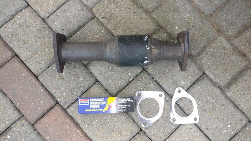
To finish everything I had to put the cat back on. To seal the gap I bought some exhaust paste to go with the new gaskets.

With not having any oil to fill the engine back up with I couldn’t start it to hear what it sounds like or to cure the exhaust paste, but I’m happy I don’t have to do that job again for a long time!
You are commitment personified with this project!
More great work. And well documented. Must be very satisfying to se such steady progress.

Well I wish it would be going quicker! Don’t want to miss out on driving it in the spring but need to get it to the body shop as soon as I can. That should be most of the more mechanical bits done before the bodyshop anyway.