Brilliant update. Really useful info. The aircon man interests me as well. I wonder how many aircon pipes he could make …
![]()
Brilliant update. Really useful info. The aircon man interests me as well. I wonder how many aircon pipes he could make …
![]()
Yep hopefully he comes good, I’ll be sure to feedback once we have a conclusion. If nothing else, I think he can help get me in touch with the right people. I’ve rung up about 30 hydraulics places (who knew North Yorkshire had such a demand for hydraulic engineering shops) and nobody will touch AC. I’ve found one mail-order place, but their indicative pricing would make me just want to sign up for the backorder queue with Lotus…
I checked his FB page out and he’s done a couple of pipe replacements recently on campervans which tend to have pipes running under the car. He’s converted from the ally pipes to rubber/barrier pipes for better longevity so that’s also an option for me.
Quick update on the AC - Stuart (link above) has been for a look today and he’s got a plan. The main complication with the damaged pipe is that it contains a pressure relief/blow off valve to protect the system in the event of a fault. That stops us from just running a replacement soft hose and means that making up a replacement hard line is a little more complicated.
The plan I think we’ll go with is running flexi at each end with a small hard section containing the (existing) pressure relief valve in the middle. My Chargecooler hoses have also congested the area more than I first appreciated, so running the original hard pipe may be a challenge in itself anyway!
I need to write/format my next big update as I managed to make some good progress over the weekend in other areas.
ETA: Not that it should matter, but the fella is clearly a petrolhead… and he also has an old Elan tucked up somewhere waiting for a few restoration jobs! It came off the road in 2011 for a minor brake refurb and it just never got finished. Hopefully I’ve bullied him enough to put a few garage hours in and get it roadworthy this summer!
Sounds like progress!
I managed to get a few bits done over the weekend, but slowing down now as I know I can’t get the car properly buttoned up until the AC is sorted and I’m actually running out of jobs to get done!
With the hoses trimmed and clipped up at the front of the car I now needed to map out my routing at the rear. The shorter of the two sill hoses would be connecting directly to the charge cooler unit closest to the boot, so that was a simple route over the roll-over bar (to stop it catching the aux belt/pulleys) the longer hose would be connecting to the outlet of the pump.
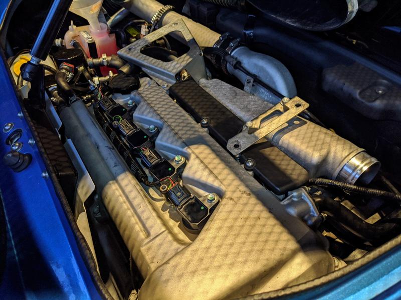
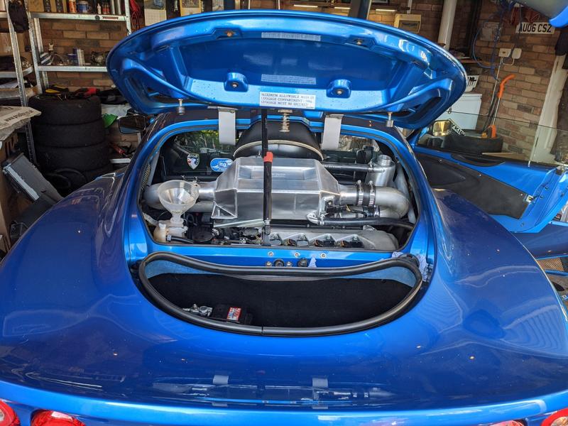
To help mock everything up I started refitting the engine mounting hardware.
You might notice a funnel in the coolant header tank in the background, over a few days I had been very slowly “gravity bleeding” the system to try and get a head start on the proper bleeding process.
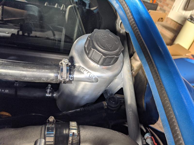
I also fitted the header tank, this was bolted to a supporting bracket of the roll-over bar.
With the charge cooler mounted to the top of the engine, and header tank fitted I could start mocking up my hoses. Obviously being very keen to not over-trim them… The sequence of components is:
header tank bottom port → pump inlet → pump outlet → long hose to front → pre-rad → not quite so long hose to rear → front port of CC → rear port of CC → header tank top port.
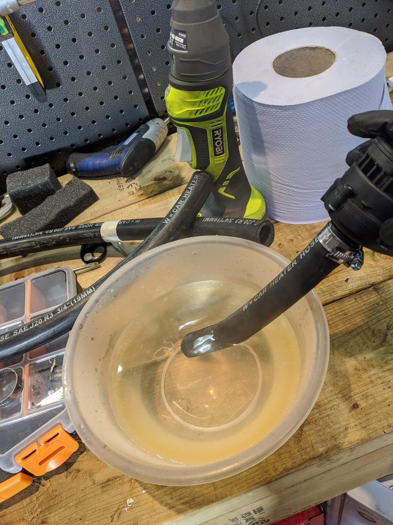
The hoses are a rather tight fit, so a nice bath before installation helped things along nicely.
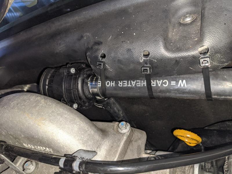
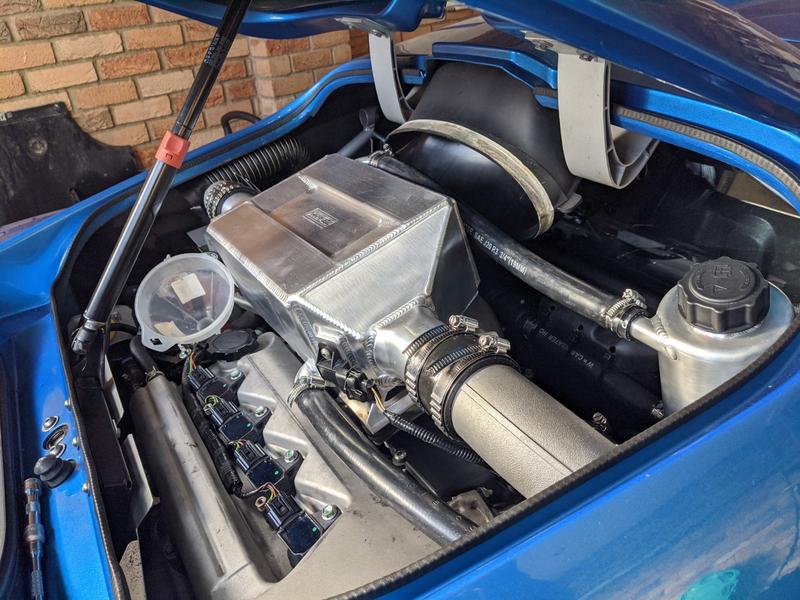
The pump is a very dinky unit and is designed to be suspended by the plumbing alone, but I found a convenient place to mount mine under the top lip of the bulkhead trim. The bulkhead is carpeted so should dampen any vibrations from the pump and the highly engineered cable-tie support will stop it from bouncing around off of the inlet manifold.
With everything trimmed down, the setup started to look half decent:
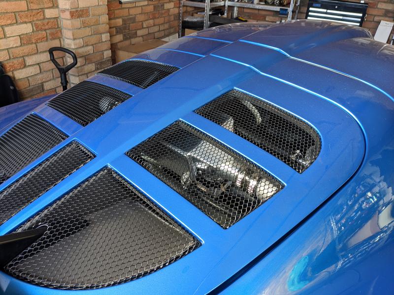
I’m still not sure whether I like the CC in the brushed ally look that it comes in, or whether I’d prefer it in satin black to make it a little more subtle. I think I’ll take the year to make my mind up and either paint it or leave it next winter. I think it looks a bit too blingy with the hatch raised, but when lowered it stands out just enough to let you know it means business…
The funnel part from the roof scoop will be remaining in place as I believe it’s bonded in, and it’s a bit of a one-way decision to remove it. I’d always like the option of returning to the air:air system in future.
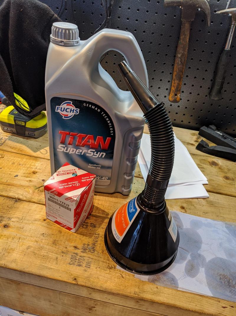
With jobs running out I did a quick oil/filter change ready for the process of bleeding both coolant systems.
The plan was to leave the CC pump disconnected whilst I concentrated on getting the main circuit bled, with the heater matrix and rad being completely dry I expected this to be a bit of a pain in the arse. After a couple of sessions of running the car up to temperature I seem to have a hot heater circuit and heat in both end-tanks of the main radiator… so I don’t think I’m far off now. The fans kick in as expected, when expected and they’re blowing air in the right direction which is a bonus!
Next up is the CC circuit. I want to run as little anti-freeze in this as possible just to maximise the efficiency of it so I’ve been testing it along the way with a tester. I’m aiming for a basic -7deg C of protection and the rest will be distilled water, and a bottle of (snake oil?) water wetter for good measure. It’s looking like 2L anti-freeze, 2.5L distilled water and 0.5L of water wetter being my final mix.
I filled up the header tank and allowed a bit of it to drain through via gravity. With no bleed screws or other openings, this obviously wasn’t going to work well for long. Whilst letting it dribble through, I got on with the pump wiring.
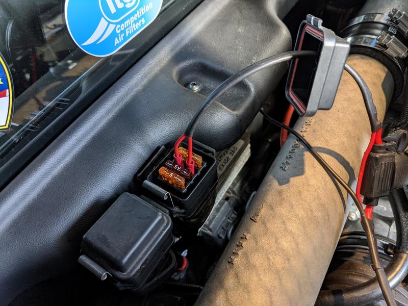
The kit from Pro Alloy includes a little piggyback link which is attached to an engine bay fuse. The fuse specified by Pro Alloy is a 10a fuse in the inboard most fusebox which according to the Exige manual is for the Injectors and Ignition coils.
The harness has an inline fuse holder so the circuit is still protected, and on the other end is pinned up for the bosch pump with a final tail to be grounded somewhere.
I got everything wired up and used a ground on the ECU mounting plate, all in the same area and very close to the pump which kept everything nice and tidy. With the ignition flicked to ACC, the pump whirred away so at least something was working. I peeked into the header tank and saw no evidence of coolant moving around at all.
I left it going for some time and still no evidence of any coolant being pushed around. I was beginning to fear a kink or blockage somewhere so I took the top hose off of the header tank and blew an airline through the system backwards. Sure enough coolant came splashing though the other end after a few seconds - so the system seemed to be clean.
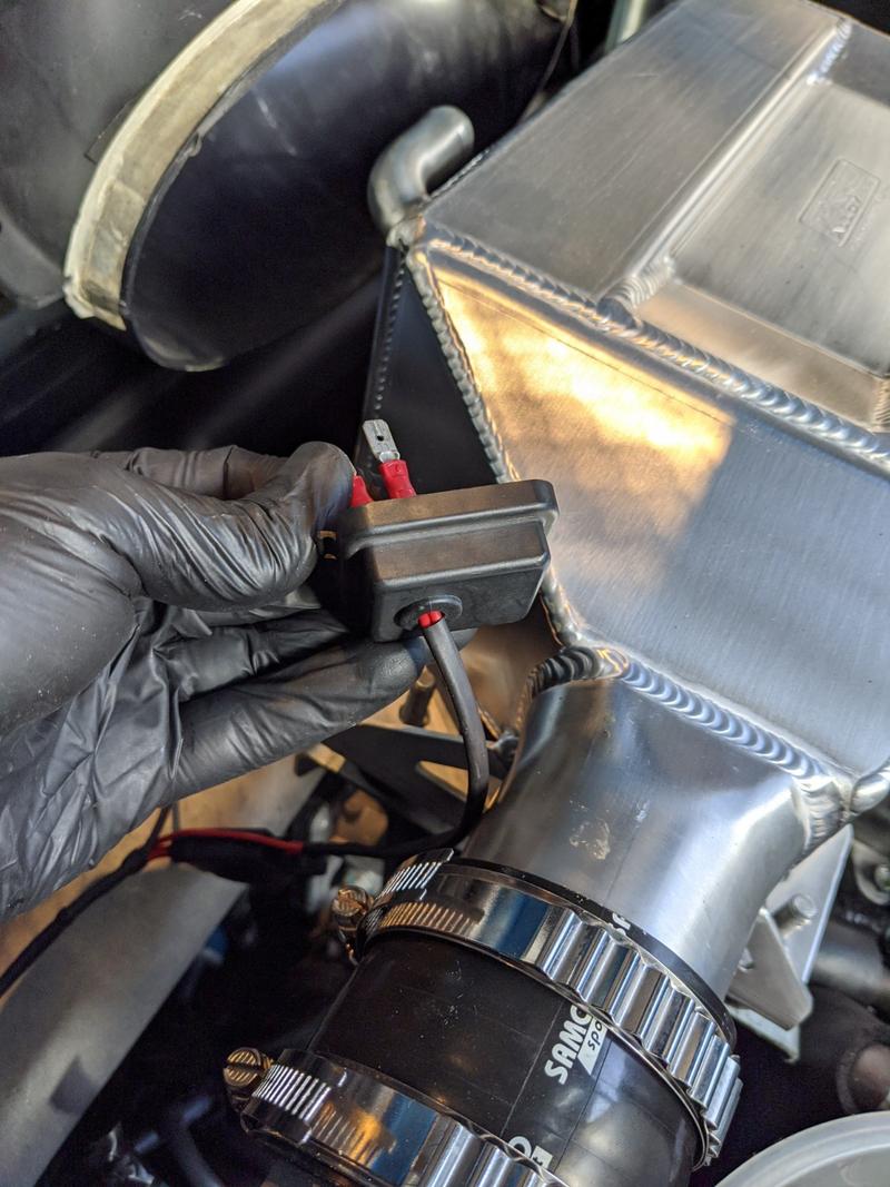
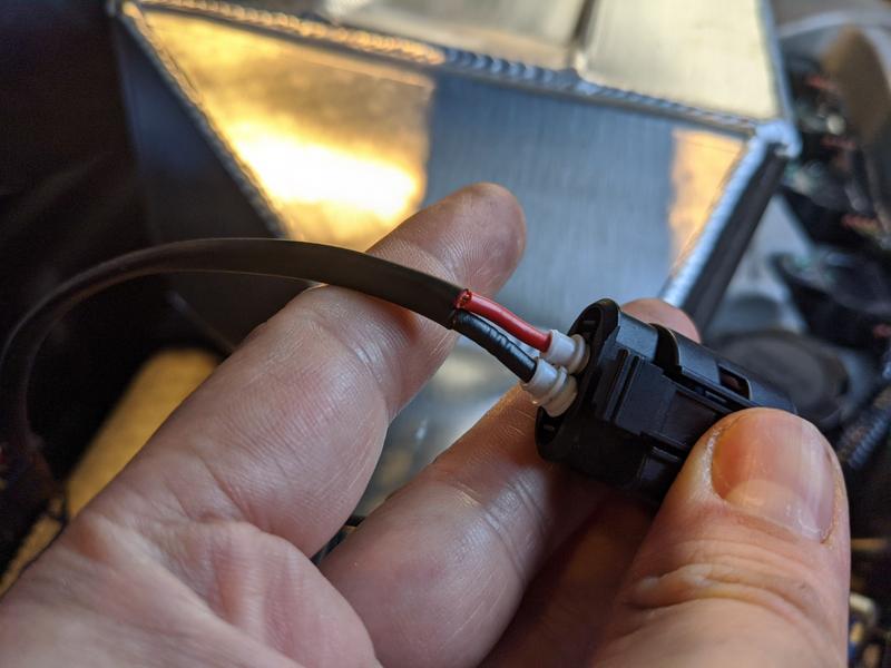
I wondered if the polarity was wrong on the pump, so took the wiring back out for a closer look and found a few questionable bits.
When the 2-core cable was stripped it looks like the sheathing on the wiring was also cut, exposing the cores. Also the rubber seals for the plug are in backwards, and not in properly at all. This made me wonder about the quality of the crimping and whether I could potentially have a dodgy connection. I can hear the pump going, so it clearly works - but the flow (when held in open air) is very very weak.
Pro Alloy support throughout this install has been amazing, so first thing on Monday morning they got back to me with some pointers for further bleeding the system as the pump is just not designed to push air, and hence it probably feels very weak. They also agree the wiring isn’t great so they’re sending me out another plug. Happy days.
I’m going to try and force a bit more water into the system by lowering the front end of the car to the floor and filling the system backwards with a funnel. Hopefully that combined with rewiring the plug will get the water moving around nicely.
Whilst tidying up some of the interior trim I dismantled, I came across a casualty of the install. The back-end of the door switch (that controls the alarm/interior light) had been knocked off by my hose wrangling. The back of the switch is broken, but luckily is readily available and costs <£10 - so got one of those on the way, then the interior can go back together.
I’m thinking of setting a date for getting my geo sorted (remember all those posts back when I fitted new suspension? Feels like a lifetime ago…) to encourage me to get a move on.
I’d still suggest adding in a second pump, it turned what was a low volume of water going through the system, to what I considered a good flow.
Also provides some redundancy. Oh and the pumps should not be run without water, it is design to use the water as it’s lubricant ![]()
Nice install by the way, over time I modified mine to use 90 degree bends in place of trying to bend the very strong pipes proalloy supplies, it just takes some of the pressure of the fittings.
Cheers Ade, yeah I only ran the pump in thin air for a few seconds just to check the electrics. Once I plumbed it into the car, it wasn’t run until the header tank was filled - and the pump was only a few inches down stream from the coolant in there so I’m fairly sure the innards would have been submerged and lubricated.
I’m not ruling out the second pump, just wanted to get the install up and running as-is and then take some benchmarks. I particularly like the idea of having the redundancy of the second pump, but as I think [mention]andybond[/mention] mentioned in another thread, more flow doesn’t always = better heat transfer, there’s a sweetspot. (I just don’t know where that is ![]() )
)
Quite early in the install I decided there was a lot of potential for 90deg connectors making this cleaner and easier. As it is I’ve managed to keep all of my bends quite “swoopy” but if I was to do this again in hindsight I’d probably stick some 90deg connectors inside the sill right near the front to get the hoses out into the open a bit cleaner, and I could probably shave a foot of hosing off the install if I installed a 90deg from the header tank facing down to meet a dangling pump and the feed pipe for the sill. All improvements I plan to make over time.
Sort of on that note, have you found a reliable way to drain the system of coolant before chopping and changing the pipework? I’m concerned that my sill run is the low point of the system and is likely to collect water, I’d like to avoid having loose coolant sloshing around my sills if I need to make an adjustment. I’m thinking of setting up an airline attachment so I can just blow it all out when needed.
I left the pipe work alone in the sills, I used the 90s to ease the connections to the rad mainly, this also allowed a better line from the rad to the bulkhead again easing some strain on the connections, just didn’t want a fracture of the inlet or outlet of the pre rad as it is just such a ball ache to get to.
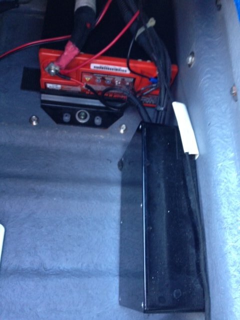
Final thing I did, well John at JSR did, was to use ralays to run the pumps from the ignition circuit with a direct fused feed from the battery, I just didn’t like adding the pumps to that location in the electrics, thought it was better to run then directly and leave alone the car electrics as much as possible.
He did all this when he fitted the gearbox cooler, ended up with a relay and fuse box in the boot for all the extra electrics just next to the battery.
Yes the pre-rad connectors are IMO the biggest chance of a hose kinking when hot due to the tight routing there, they would indeed be a good spot for 90deg connectors. I may do that before the clam goes on, as it may actually tidy up that area in time for the AC man to come back and fit (yet another) pipe in there.
I’m also thinking I could pull a few inches of slack out of the sills, chop the hoses on the outside, fit a 90deg connector to each and then pop the new right-angle back through the hole and poke the grommet back in afterwards. That would also take out a high kink risk.
ETA: Did you get plastic/nylon connectors or did you find some metal ones?
The Relay/Direct connection is the ‘traditional’ way to wire this setup up. I’m good friends with a VXTurbo owner who chargecooled his a couple of years ago and he went down that route. If my pump still isn’t pushing any fluid through after I have another stab at the electrics then I think I’ll go down this path and just sort it the “old fashioned” way. I’m really no auto-electrician so I don’t fully understand the concepts and differences between the Pro-Alloy “piggyback” route and a relay/battery route though. (I know how each one works, I just don’t know the pros/cons of each compared to each other).
I think I found the 90 bends on ebay and they were plastic/nylon
for me it means you put back the electrics as lotus intended rather than taking a feed to power the pumps from a circuit not designed for the continuous load. Offsetting that load directly via a relay to the battery seemed the best choice and JDS fitted it in a nice tidy box in the boot. It also meant I got to use correct power connectors for everything making it look OEM style
Cheers Ade. I think I’ll be going for a poke around a certain VX220 engine bay soon to check out the wiring.
Same idea as this How to rewire install fuel pump relay mod but obviously the control wire (red fuel pump power wire) would be the one you currently have from the proalloy kit that is destined for the current pump. Nice and simple to do. Just put the fused for the power for the main pump as near as it reasonably possible to the battery.
no idea what was in the box LOL
^ I have a picture somewhere. His name is Freddy, and was a particularly energetic mouse from the local pet shop. I think on the invoice it said ‘wiring and relays and stuff’
I hope you fed him regularly!! ![]()
In all seriousness, main power feeds for the pumps went from the battery, fuse, through the relay and onto the water pumps. Relay control was via the ignition feed from the switch live at the reverse light switch.
Also had gearbox cooler pump circuit that was a similar set up, but switched via a toggle switch on the side of the box.
As we didn’t trust Ade to remember do it, the switch also fed the mouse ![]()
Cheers Team, all sounds simple enough - and that’s a nice tidy install in the boot.
I intend to go to a smaller formfactor battery at some point so I’ll probably look at implementing the relay approach at that point - should be able to make for a nice tidy install in the existing battery cubby.
I got the new plug from PA yesterday so got to work rewiring it, did a much tidier job but I’m still seeing a rather poor flow rate through the system.
PA has commented that the pump is not designed to push air, so any air in the system will really weaken the flow but I’m not sure what else I can do to bleed it out. I’ve run a hose through the system backwards (so in through the outlet of the CC unit, to the front of the car, into the pre-rad, back up to the header tank via the pump). As soon as I turn the hose on, the water level in the header tank starts rising with no bubbles.
Am I expecting too much from the pump? I’m expecting to see a fairly constant flow of water coming back into the header tank but I’m just not seeing anything. I took the return hose off the pre-rad at the front of the car and I got a half decent flow out of that… but nothing too dramatic, so the flow is at least getting to the front of the car.
If I dip my finger into the header tank I can just about feel a slightly swirling of water - but you can’t even see disturbance on the surface of the coolant so it’s nothing strong.
Once the garage floor is dry I’m going to triple check for kinks on the hose going up to the pump, but everywhere else is clear as far as I can see.
EDIT: DUNNIT! It must have been air, I took the return hose off the header tank and aimed it into a cup, started the pump going and then put my mouth (yes, my mouth) over the header tank opening and blew into it. After a few splutters the pump drastically changed tone and water came spraying out into my cup. Quickly re-attached the hose, topped header tank up - job done!
Excellent news
This weekend I will mostly be looking at my setup and validating if I need to blow into the expansion tank.