Just had a look again at the pics . . .it’s a wonderful piece of work, please keep at it.Hope to hear and see it at full throttle in the (not too distant)future.
Pat- just to add my own words of support! Fantastic project and surely worth the occasional setback. As you said, most things went okay; and if you can solve the shaft breakage issue then there could be a good few £££ to be made flogging ‘improved’ shafts to Ferrari owners…
I had a look around on the internet and found this:
http://www.fcars.co.uk/forum/showthread.php?14645-355-Flywheel-Free-wheeling
It’s probably an article you’re read already but it got me thinking - were both your shaft failures in the same place as those in the link? To me the seal grooves look very marginal on corner radius blending which could lead to a horribly localised stress point with either a snap torque or misalignment/harmonic flex.
Very interesting post in that link…
here is a copy/paste of what has been said
Some months ago now Terry sent us the old broken shaft to have a look at. The first thing we done was to check the hardness of the shaft across the break. We were quite surprised to see that the shaft was measuring between 58-60Rc right the way across. In non technical terms the shaft was very hard right the way through. What happened to Terry’s shaft was only to be expected with something as hard as this all the way through.
If we would have designed this shaft we would have used an alloy case hardening steel which after heat treatment would have had a hard outer and a tough inner core - this is the industry standard on this type of component and can only think that Ferrari have used a through hardening steel and forgot to temper these shafts back down to a level of hardness that would be hard enough and yet tough enough to withstand the shock load that they are subjected to.
We was going to send the shaft to our metallurgy lab to get an analysis done on the material, but after talking to Terry we both agreed that the cause of failure was the through hardness of the shaft and could have failed at any time.
Thanks guys, yes I had read that, and yes they all fail on the seal grooves, which have almost no radius. I’m considering whether a radius can be added there without affecting the fit of the gearbox oil seals too badly.
As for the hardness thing, it is possible Ferrari made a cock up… I tend to think it’s more likely that the shaft works fine when all is as Ferrari intended though. I suspect the failures on Ferrari’s are down to poor maintenance of the dual mass flywheel (keeping it free’d up, clean and well greased etc), the jury is still out on the cause of the failures on mine, but most likely are:
- a change in the driveline stiffness causing something to hit a resonant harmonic frequency, possibly my use of a hub dyno rather than a normal rolling road with tyre may have made this worse.
- or possibly, just the fact that during all the initial engine setup there have been a number of large backfires (inevitable really when setting up fuel and ignition for the first time on such a large engine) and these backfires might have put some unusual shock loads into the drivetrain.
Will keep the thread updated with any developments ![]()
The seals are the ones listed below as ‘spigot shaft sealing ring’?
If so, then I wouldn’t see any reason not to change to using viton o-rings which would then allow the groove to have a curved internal profile and so avoid the sharp radius that’s present on the standard shaft.
I was under the impression hub dyno’s tend to be easier on drive line as there’s less rotating mass to accelerate than with a conventional one with wheels/rollers?
As another thought - would it be an option to do the engine mapping etc. on an engine dyno to eliminate the drive line stresses from the process?
Yep they’re the ones, that’s something I had thought about too. I have access to a huge range of O-rings so if I design my own replacement shaft its something to consider. I have found a couple of companies offering alternative shafts, one in Germany are very dear, and a UK one who are just in the process of manufacturing their first batch.
The hub dyno has far less intertia, but also far less torsional compliance as you have lost the inherent windup and damping you get in the tyre on a set of rollers.
Aside from being hideously expensive, running on an engine dyno would be an option, but in order to not require the shaft/starter motor, you’d need to run on an A/C dyno (rather than eddy current) which are mostly the domain of OEMs.
In other news I’ve had the Optical Emission Spectrometry material analysis back from the Ferrari shaft. It looks like a reasonable grade of medium carbon steel, I’m surprised at the nickel content which is making it tricky to track down it’s exact grade and hence find out the material properties.
C 0.35%
Si 0.3%
Mn 0.4%
Cr 1.75%
Mo 0.35%
Ni 4%
Cu 0.13 %
Closest match so far is SAE 3335 (lacking Moly)
Looking at the NiCrMo content though tells you it’s not some cheap steel, yes there are stronger/tougher materials available but it would only be a small improvement available.
Bad luck Pat, onwards and upwards though as everyone else has said.
You mention this is a fairly common issue, but that there are loads of mega high mile racers etc out there. Are these guys doing anything different to you?
36NiCrMo16 maybe?
I admit the Mo level is higher than the analysis results (up to 0.7% depending on where you look) but similar application for power transmission shafts, etc.
Maybe the low Mo on yours contributed to the breakage?
On the material score it does seem to go back to a design flaw around the seals and possibly poor-spec steel was enough to take it over the edge.
Thanks for the support and helpful thoughts guys!
Things are moving towards what I hope is a solution now.
I’ve bought a replacement 348 gun-drilled shaft, which everyone agrees should be better than the solid shaft and is pretty much standard practice in high-performance transmission shaft design.
Today I dropped it with an F1 coatings supplier to have some precision shot-peening applied to the groove base, radius and sides. This should put compressive residual stress into the part, making it more resiliant against tensile stress, cracking and fracture.
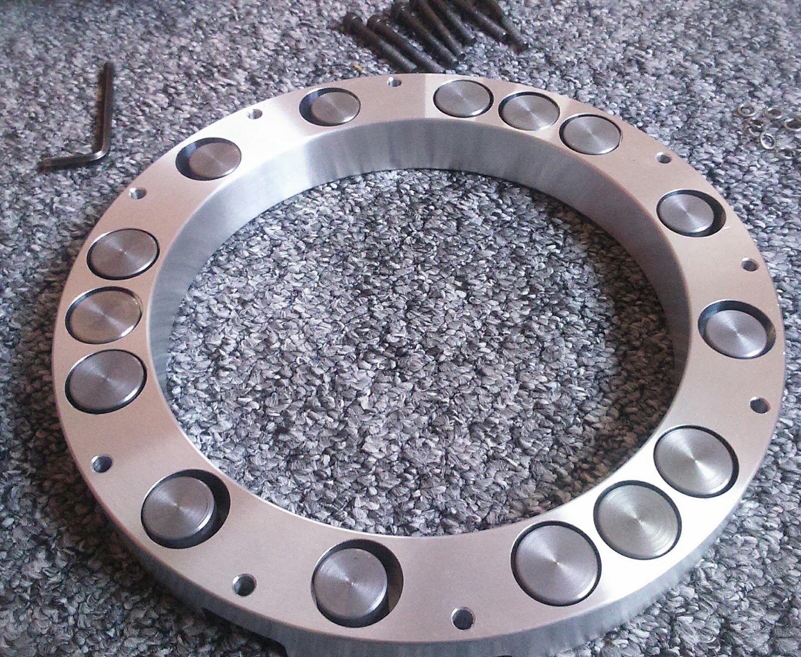
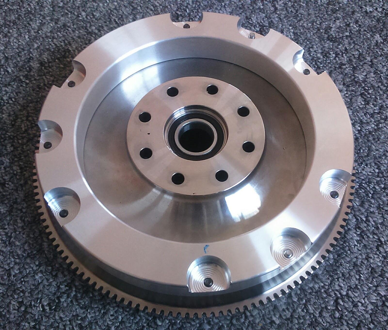
Alongside that I’ve designed a harmonic pendulum balancer which is currently undergoing manufacture:
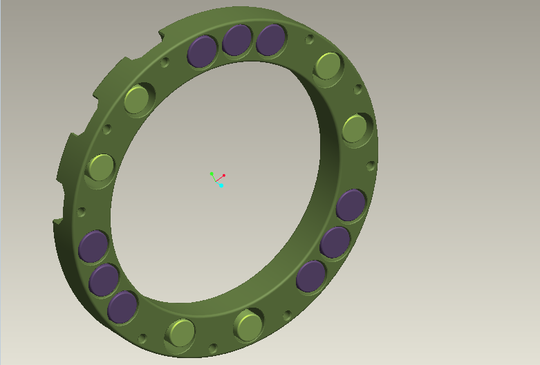
This bolts onto the flywheel and puts some inertia back on the flywheel, but more importantly balances the torsional vibrations by actually opposing their forces throughout the entire engine speed range, rather than traditional crank dampers and dual mass flywheels which can only dampen and absorb the torsional forces, (and only really work well in a relatively narrow engine speed band).
GEEK BIT. Harmonic pendulum balancers were originally developed for aircraft engines in the 1920s & 30’s and one of the most successful application was in the Pratt & Whitney Double Wasp in WWII. Since then they have gained a following in race engines especially historic engines or others with unusual firing orders/harmonics. Contemporary F1 engines use something similar on their camshafts.
http://www.mooregoodink.com/news/tag/pendulum-damper/
Once this is finished I’ll get the entire balancer, flywheel and clutch housing assembly (minus clutch friction plate) very carefully dynamically balanced before fitting it along with the new shaft.
Then we’ll try mapping again but this time on a normal rolling road.
Finger’s crossed!!!
So glad you’re persisting.
That sounds like progress…I think. Google translate didn’t help.
Maranello wasn’t built in a day. Take a break if it helps but keep the desire.
You probably can’t tell through hyperspace how much energy there is routing for you…
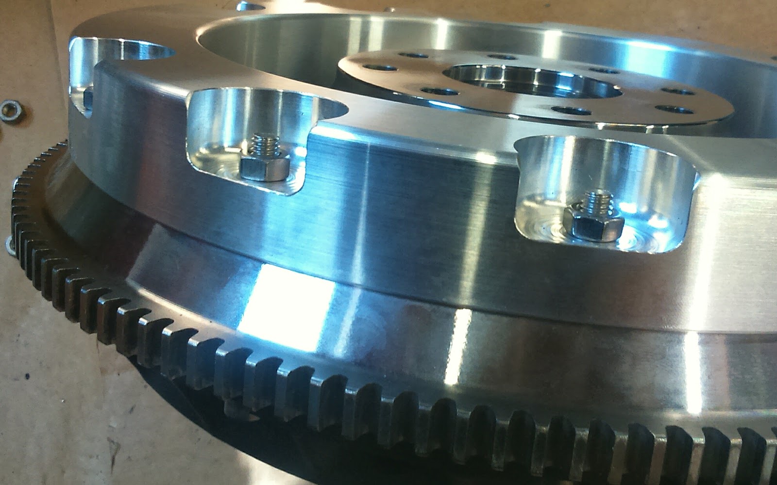
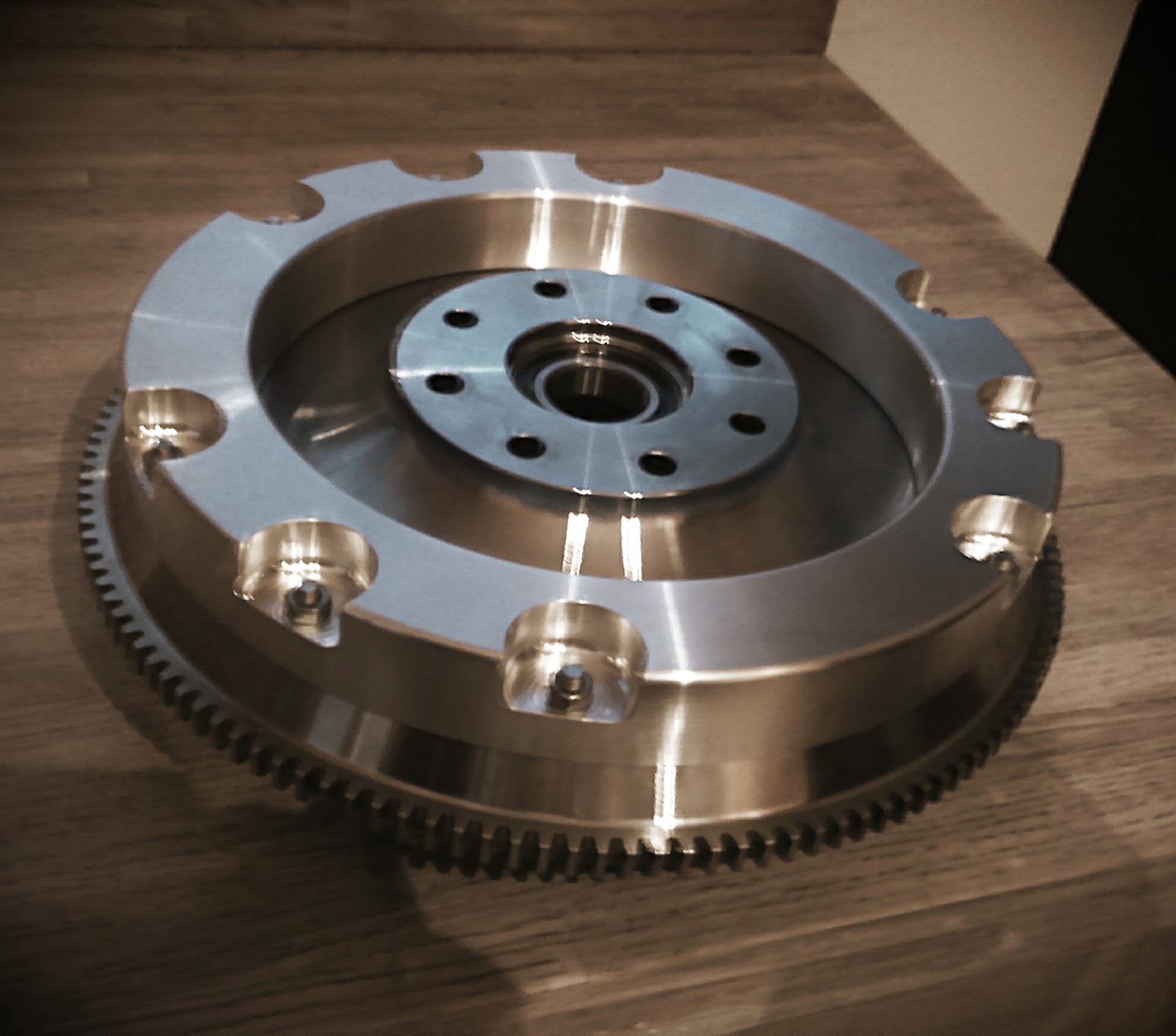
Picked it up earlier this week:
TEFLON coated the rollers and pockets (including baking on the teflon coating in an oven):
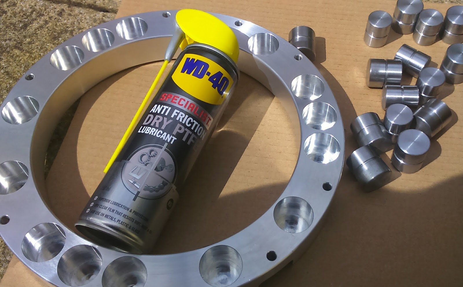
Checked weights and balance of everything. Rollers all within ±1 gram!
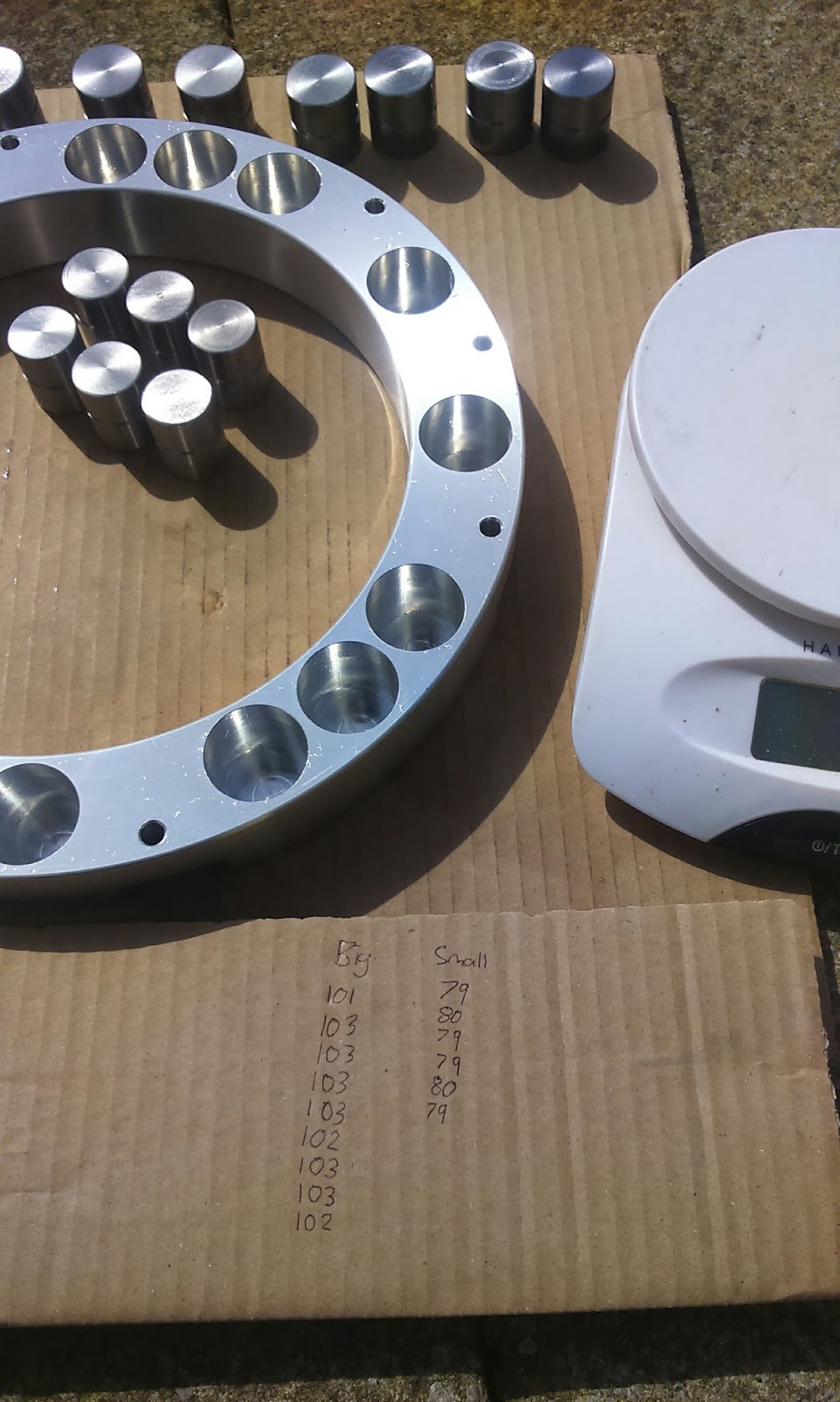
Tomorrow morning I collect the sho-peened shaft. By the end of Monday I’m hoping to have it all back together in the car. Here’s a few more pictures of mocking up the balancer onto flywheel (ignore nuts, will be replaced with flanged locknuts)
Fingers crossed this gets you past the gear box issues. ![]()
I’ll admit to only understanding about 1% of some of these post, but in awe of the engineering, knowledge and effort going into every element of the build ![]()
Fantastic work, it’s going to be one incredible car ![]()
I understand the theory.
Whether or not this all actually solves the issue is still anyone’s guess. If it’s still no joy after this (I.e if the shaft breaks again in the same place) then I’m not sure there is a viable way for me to fix it, and I’ll be back to either thinking about breaking the car, or considering an alternative 90degree V6 engine and gearbox combo.
Lets hope it doesn’t come to that!
Incredible attention to detail.
Can’t help thinking that the cause of failures must be more fundamental than slightly incorrect grades of steel or engineering imperfections …
Trying to think outside the box , not frowning on your work .
In my distant past I recall a few shaft breakages and harmonic balancer issues . This was in the aircraft sector though not cars .
There’s a guy called Nigel Beale who’s the UK importer of Rotax aero engines , very technically competent .
Maybe worth a chat ?
Just trying to help thats all
Finally back to life and sounding good :twisted:
F355 - engine blips - YouTube
Ooof,…that’s amazing Pat!
11 out of 10 for perseverance ![]()
Well done Pat.
[quote=“pat_t”]Finally back to life and sounding good :twisted:
F355 - engine blips - YouTube[/quote]
Wow ! just awesome , hats off to you an this amazing project ![]()