2007 Lotus 2-Eleven

Little bit of festive progress.

Finished off the bulk of the oil leak work. Got the block about as clean as I could.

Looking a lot fresher with the scrubbed up pulleys too.

I replaced a crush washer for the OCV filter, and cleaned the filter itself.

Next up was to make a decision on the pile of rear suspension components I had. I was kidding nobody, as soon as I removed them to get the subframe off I knew a refurb was on the cards - so I got to work removing the rest.

Found some weirdness, the car has certainly had a suspension refurb of sorts before. Pretty inconsistent with approach though, and front/back possibly done by different people at different times.

Found a half drilled out balljoint with what looked to be a polystrene ball glued into it. No, I don’t know either…

The camber/plinth bolts I guess had been replaced but one found to be too long… so it was ground off instead of just using the correct size. Hey ho.

Nothing glaring, but a few other bits - washers missing from certain fixings, weird bolt sizes, etc. Be glad to get it all off and know it’s up to spec even if nothing was ‘dangerous’ as such.

Fronts have had paint before, it’s not a bad job - but as you can see the rust is starting to show itself again.

Pressing BJs out:

…and bushes.

Dead easy with the right tools.

I’d be replacing with Nitron solid bearings, supplied by Dave @ SL as part of a full refurb kit it also comes with fresh hardware, balljoints, track rod ends and drop links.

Ready to go:

This will be my fourth wishbone refurb on a Lotus, each time a different method used.

Elise - Powdercoated everything. I still ‘know’ the car, and it’s weathered pretty well. Making sure the interference fit faces are masked/cleaned is the hard part here - and grinding powdercoat off afterwards is a bit of a 'mare.

Exige #1 - Zinc Plated with clear lacquer over the top. I loved this finish when it was new, bearings/bushes bolted right up and it looked very spanking-OE. Unfortunately it just didn’t last, and by that summer it was showing corrosion coming through so it needed redoing.

Exige #2 - POR15 brushed on. Very messy, and difficult to do in a garage in Winter as it likes a bit of warmth. It is however fantastic, it self levels and looks as good as powdercoat - and is solid as a rock. I would have done this again, I just can’t be bothered.

So for the 2-Eleven I’m reverting to powdercoat, with a small upgrade in that the uprights and bush tubes will be done with a ceramic coat so there’s no interference issues. Recommended by Jonny @ Performance Autocare and I’ve seen a few recent examples, and it looks rather nice.

I’m at peace with no solution being a fire and forget. If I have to redo it to make it mint every few years, then so be it.

With the wishbones gone from the garage, I tidied up the steering rack and replaced the track rod ends from the SeriouslLotus kit.

Another small job, I fitted some new studs ready for the exhaust manifold.

Exhaust will go on next, followed by a tiny bit more wiring then I can finally look at writing up the ECU install.

This is fantastic.

Cannot wait for the next instalment

Waiting for the dry ice cleaning kit phase.

1 Like

Few more bits sorted out this week.

I dug out the 2bular manifold and 200cell cat from my Exige.

It’s now on its third(!) ceramic coat, as it’s just kept failing. The original two coats were a proper thermal barrier coat but I found it both underwhelming in performance (compared to a quality wrap) and it failed and started flaking off both times. The company who applied it of course were great about it, and redid it FoC but it was just the cost of effort/gaskets each time grinding me down. In the end we decided to just call it a day and go for an aesthetics coating (cerakote) as I couldn’t trust the other coating to keep the temps where I wanted them.

This way, the exhaust looks decent (for now) and I can handle heat through other, known quantities.

I won’t actually be wrapping it, the 2-Eleven is a lot more ‘open’ at the back than the Exige was with no real close proximity to bodywork. I’ll be protecting the bootlid with some gold tape, and that’s about it.

Alas, it wasn’t straight forward. I’d previously hand tightened in the new studs - and when I went to apply some torque to the nuts, the top/middle one pulled out a thread. Grrr.

Still, I’m finally becoming a bit of a dab hand with the old helicoil kit so I had it repaired pronto.

It’s quite an enjoyable process when you have access, though I’d still rather not have to do it…

Finally on, looking good.

Next up I wanted to get the cam cover off. I could swap the last couple of seals for my oil leak investigation and also do some of the recommended 2ZZ-GE checks.

Some of the engines suffered from a cam wiping issue, my Elise had it (though it went undetected during my ownership) but both Exige and now the 2-Eleven have survived. It seems to be something that happens within 20k miles, if it’s going to happen at all. If left unchecked, it eventually destroyed rockers and caused all sorts of chaos but luckily it’s not something I need to address here.

There are also a couple of bolts, known as lift bolts. Earlier designs (pre-Lotus allocation of 2zz-ge) were prone to snapping, leaving you with out VVTLI and needing to drill a bolt out of the engine. The design was changed around 2003/04 and the newer ones generally don’t snap - but it was still worth buying some for pennies just in case this was an old stock engine or something. (It wasn’t)

I did a quick valve clearance check too, all in spec. Then replaced the cam cover gasket and refitted with the appropriate RTV blobs at the timing case union.

The injector rail was lifted up out of the way to get the cam cover out, so used the opportunity to put my bigger injectors in.

They’re Injector Dynamics 1050-XDS. Way bigger than what is needed for the 2ZZ-GE but the smallest size that are readily available from ID. So good are they, that even at low duty they’re very accurate and don’t carry the old problems of crappy idling with an oversized injector. There’s simply no point in ID producing smaller injectors anymore because these are so good.

I bought them for the Exige mainly because I couldn’t get good injector data for the OEM ones. With these in, the ECU can be calibrated precisely and that makes me feel good inside.

Up next, I got my goodie box from Pro Alloy.

This is really the whole reason for taking the car apart, everything that’s happened since has been scope creep.

I retained the Chargecooler setup from the Exige, but due to the engine bay layouts and totally different clam setups, it won’t fit into the 2-Eleven. Pro Alloy have been fantastic in agreeing to sell me just the bits I need to modify the kit and allow me to recycle it. In hindsight, it really wasn’t worth the effort. Keeping the Exige chargecooled and buying a fresh new kit for the 2-Eleven would have made much more sense, but at the time of stripping the CC off of the Exige - I wasn’t exactly sure what I was going to do next so it made sense at the time.

The key differences are that the CC Core can no longer sit on top of the engine. The same applied to the OE intercooler and Lotus addressed this with some brackets that attached the IC to the engine/gearbox housing, and sat it up above the exhaust manifold. Early Pro Alloy kits just reused these brackets as far as I know, but they were already known for snapping even with the air IC, so adding a few kilos of coolant to the load accelerated that.

The kit ended up moving the CC core further back and rigidly mounting it to the subframe.

What neither myself nor Pro Alloy appreciated when planning out this conversion, is that Lotus altered the exhaust heatshield design on the 2-Eleven. I think this happened when the production of the car moved away from the Lotus Motorsport department into the factory proper. Pro Alloy developed their kit on a later, non-MS car and my car was the last of the MS cars… so the kit wouldn’t fit.

This is the PA development install. The blocky heatshield with the blue X on it is what they used for the rearmost mountings for the core.

Compared to mine:

My heatshield only really rigidly mounts at the leading end and just flaps around until the clam is back on. Would be no good for supporting the weight of the CC.

This leaves the back of my CC unsupported.

With the 2-Eleven being such a low volume car, and my kit being a bit bespoke due to the Exige conversion I was expecting some installation challenges and PA have stepped up and are being excellent. Throwing ideas around, we think we have something - but it’s on me to sketch up something vaguely accurate now so they can make it for me… so we’ll see how that goes and I’ll update when I have something!

It really is a nice kit though. The boost pipes are very light compared to the OE ones

I asked for a small customisation by way of the MAP sensor takeoff from the hot side pipe.

Header tank is unique for the 2-Eleven too, it tucks under by the fuel filler cap with a little goose neck filler with a lovely knurled cap. Much better than the plastic one that the Exige had :slight_smile:

…and finally the pre-rad and fans. I could have used my Exige one here, but this one is a slightly newer design and has the fans on the underside rather than the top puller fans my Exige had (due to clam clearance) so this was just simpler to add too, rather than trying to reverse engineer the Exige one.

The CC stuff is all packed away again for now, I’d like to finish off all the jobs that I’m part way through before starting another one!

The ProAlloy kit is fantastic. I knew you couldnt resist getting the car chargecooled!

I am assuming you will map the car yourself with the injectors? Or are you going to swap back out to standard, drive to the mapping place and then swap?

Last question ; do you know why the ceramic coating kept on failing? Its quite dissapointing to read after the expense that it basically wont stay on!

Cheers Andy. Yes 3 days after buying the car, I was at Donington in 38C heat and the car could barely pull itself back up the hill. Chargecooler was penned in at that moment!

I still have my map file from the Exige, so I’m pretty confident I’ll have a running, idling car when the EMU goes on. I’ll fine tune the idle whilst I’m doing things like bleeding coolant but other than that I don’t really need to put much time into it.

I’m planning to trailer it to a mapping session before the bodywork goes back on… mainly because I’m not confident the car will fit on a dyno with the clams on :rofl:

As for the ceramic coat, no real ideas. It failed in a couple of places both times - neither suffered any kind of impact or abrasion. One of the spots which failed both times was right on the outside of the bend of the manifold collector - right where all four runners merged and in the firing line of the gasses… making me think it just wasn’t up to the job and this hotspot just killed it. Very disappointing, it wasn’t cheap and for years people have been telling me that “wrap is crap, get a ceramic coat”.

It was underwhelming for both performance and longevity - so ceramic exhausts get a big thumbs down from me.

List of jobs for Andys exige

Ceramic coating

Really dissapointed to read that Kyle.

I completely forgot that you had a trailer! Silly me!

1 Like

Fascinating, as always. Lots of shiny kit. Keep up the good work

2 Likes

Amazing stuff, I love reading these updates :star_struck:

It feels like you’re really getting to know the car, especially with the inevitable scope creep :sweat_smile:

Add me to the list of disappointed people hearing about the ceramic coating not doing the job. I’ve always loved the look and assumed it would perform really well. Really frustrating, but especially so considering the expense.

1 Like

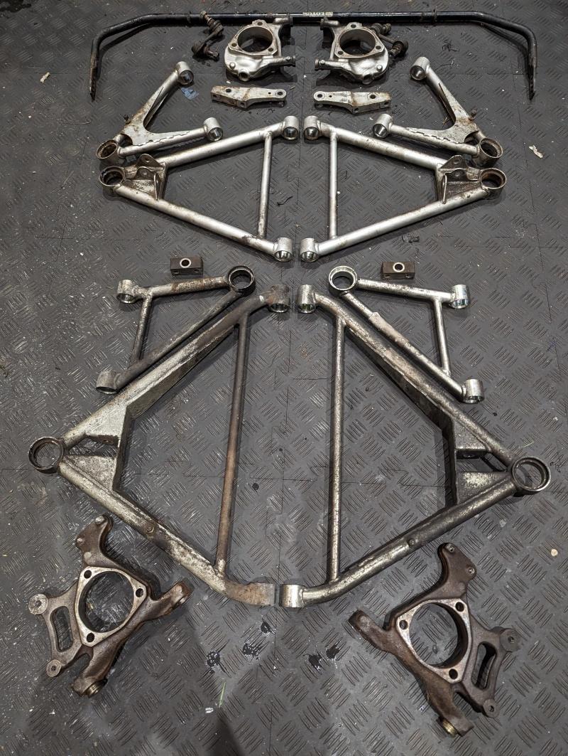
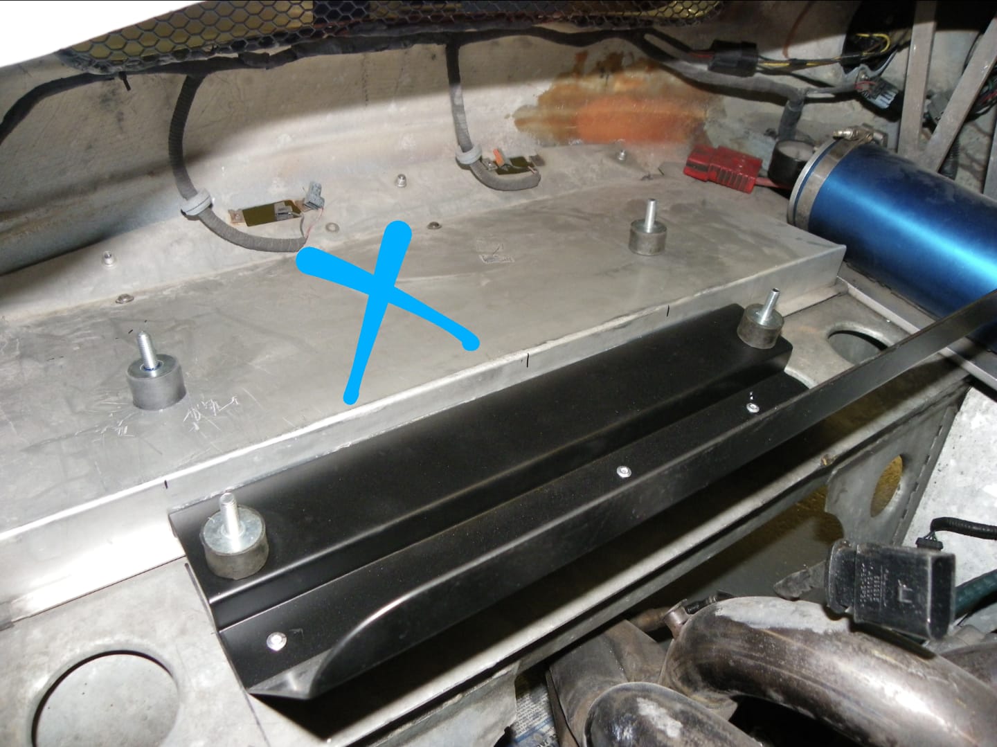
Whilst waiting for the chargecooler bracket/install to be resolved I wanted to finish a few bits off.

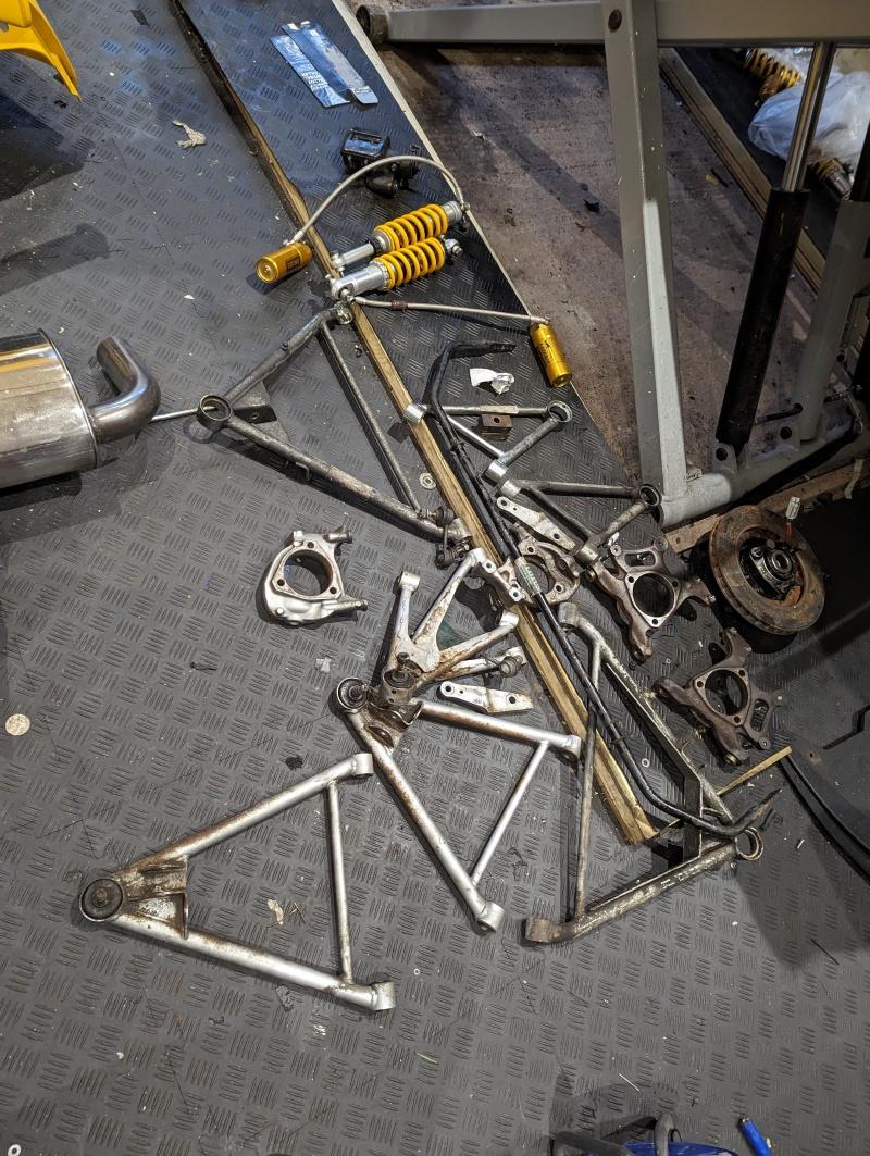
Suspension is all out of the house, so that left wiring and ECU stuff. Apologies in advance if this one is a bit long and dry, by its nature - there aren’t many photos to post here.

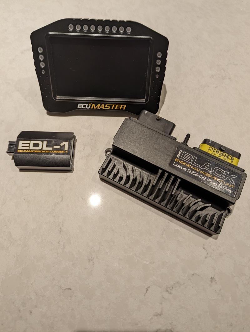
As per the theme of this thread, this part of the project would be fitting a load of parts that I took from my Exige before selling it. Specifically the small ECUMaster stack of stuff I have.

(the dash has been in since summer, but with a limited feature set because the CANbus data in the pre-2008 Lotus cars is very limited).

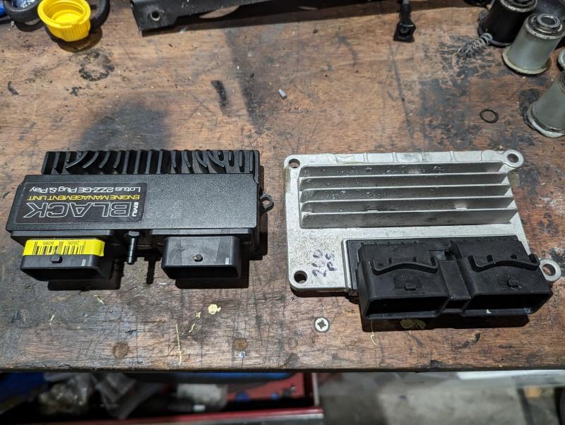
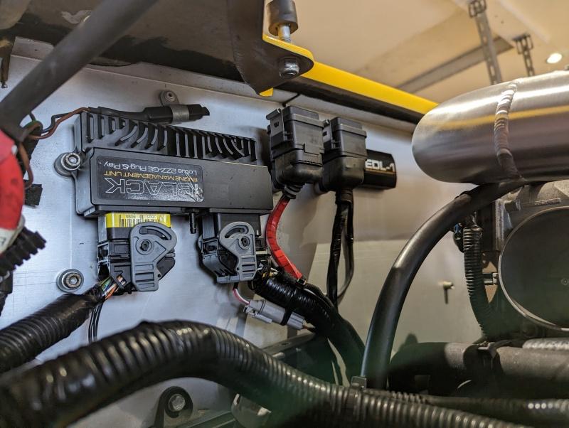
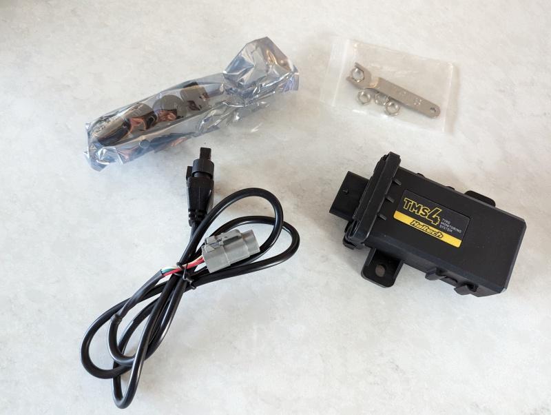
Adding to the dash would be the EMU Black ECU and the EDL-1 data logger. Not photographed are also:

  • ECUMaster GPS2CAN (lap timing etc)
  • ECUMaster CAN Switchboard (adds a shed load more I/O into the CAN network)
  • ECUMASTER USB2CAN (allows management of the various equipment via the CAN network)
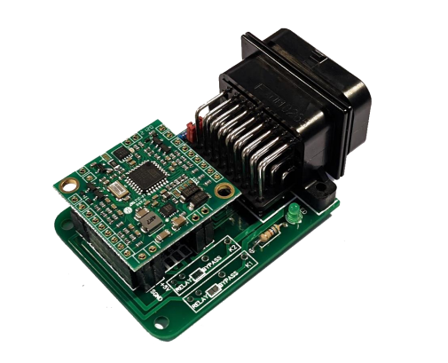
  • TPMS 2 CAN (tyre pressure and temp monitoring real time)

For anyone who’s not worked with a CAN network in a car before, they’re really a doddle. It’s just a serial bus network with a start node and an end node (can be any equipment that has a termination resistor, usually enabled/disabled by software) which in this case is the ECU and the ADU. It has just two wires, Can H and Can L. You can splice into these to create spurs from the network and add as many CAN appliances as possible. You can also daisy chain spurs, within reason. My ADU already has a spur coming from it with the GPS2CAN unit on it, so I’ll branch out of that under the front clam where there’s plenty of space to store the TPMS module and the CAN expansion module (more on that in a future post).

My goal for this car is to make as much as this stuff plug and play as possible. I do not want to be hacking into the factory wiring unless it absolutely cannot be avoided, and I want returning to ‘stock’ to be as simple as unplugging the kit and plugging the standard ECU back in.

I’ve almost achieved that goal, but with one exception.

The Lotus ABS unit sends data to the standard ECU to provide wheel speed data for all four wheels. Even though the EMU Black is a PnP unit for the 2ZZ Lotus cars, it was not pinned for the 4x wheel speed sensors because it lacked the I/O capacity. The ADU dashboard that I have acts as an expansion module, and has digital inputs to take this wheelspeed data… so I’d have to splice into the wiring from the ABS unit to the ECU, and divert it into the dashboard. The Dashboard then sends the wheelspeed data over the CAN network for the ECU to use for TC activities.

I have been thinking about this for most of the summer to try and find an efficient way to avoid hacking into the wiring, I even considered making an adapter harness for the whole ECU but ran into difficulties sourcing the appropriate connectors etc, plus the costs were just spiralling.

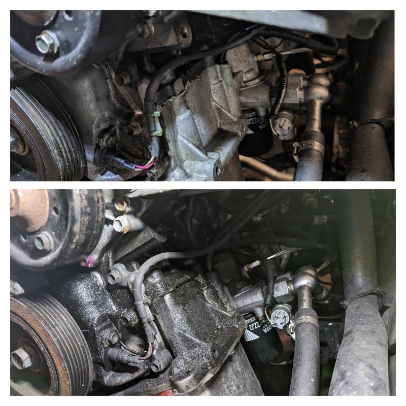
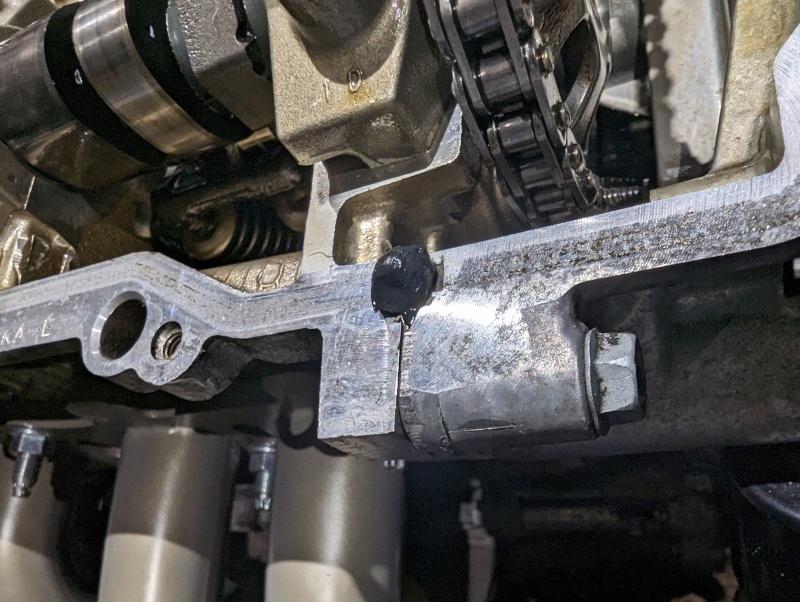
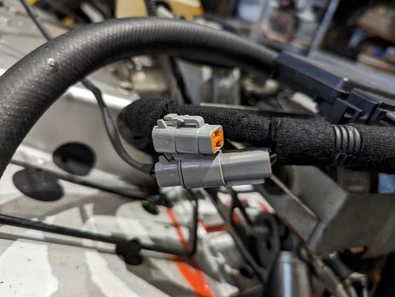
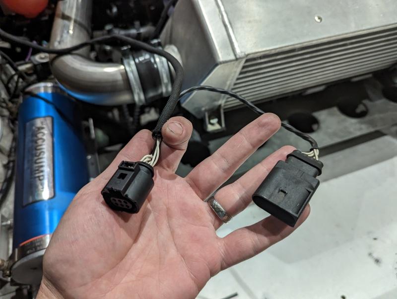
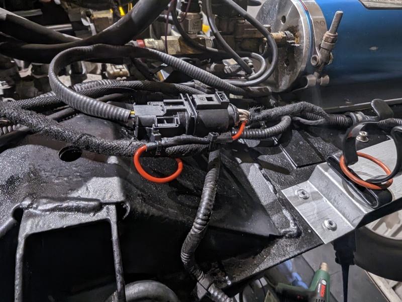
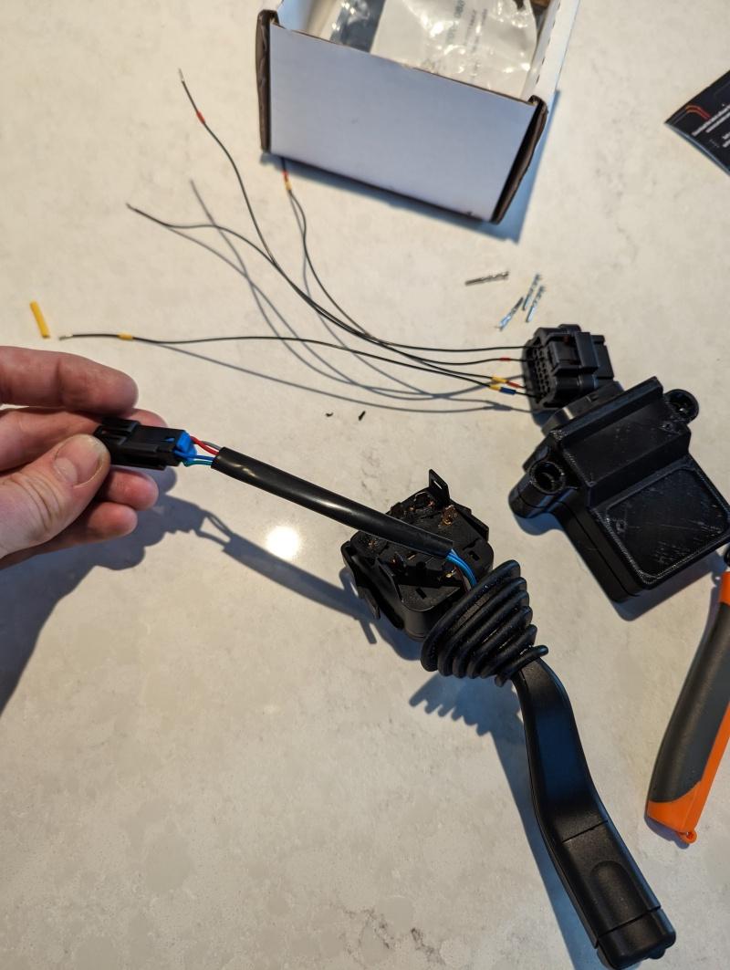
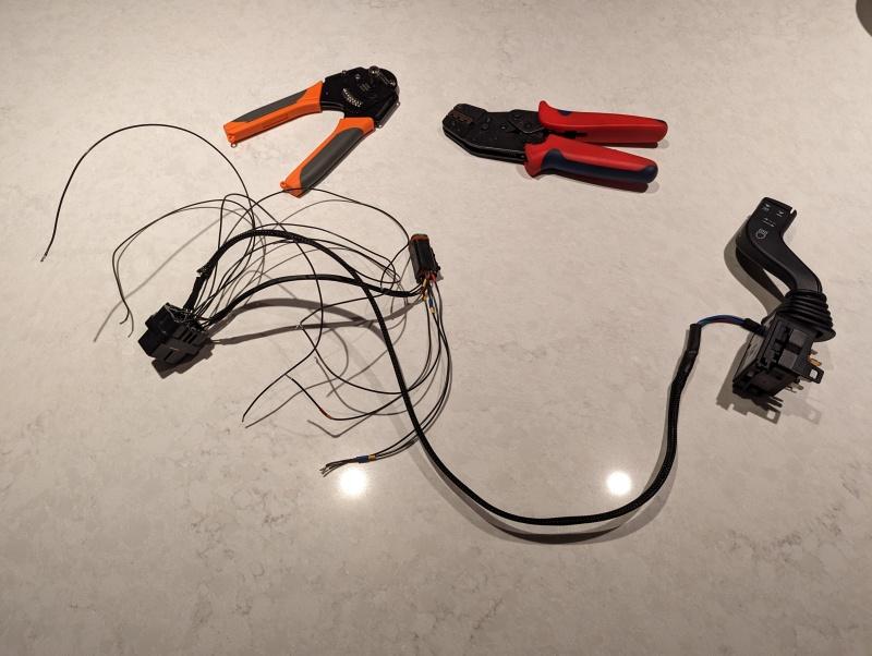
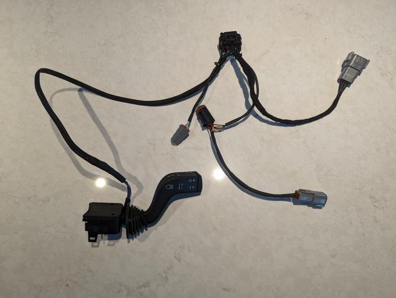
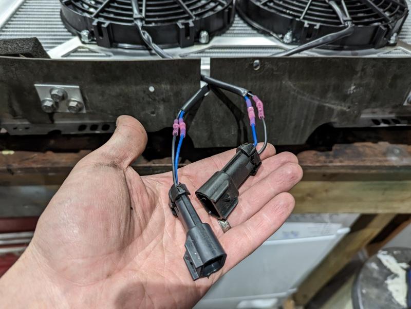
In the end, I decided I’d need to compromise here and cut the standard wiring, but I did it in such a way that I feel it’s both robust, tidy and easily reversible.

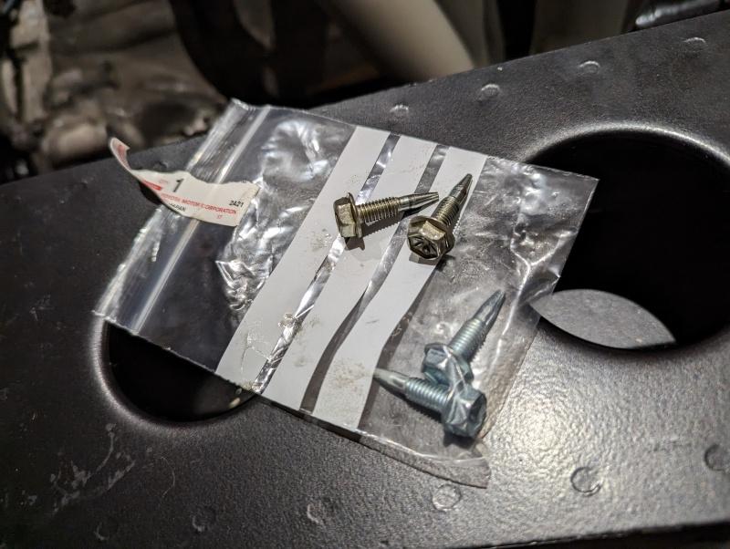
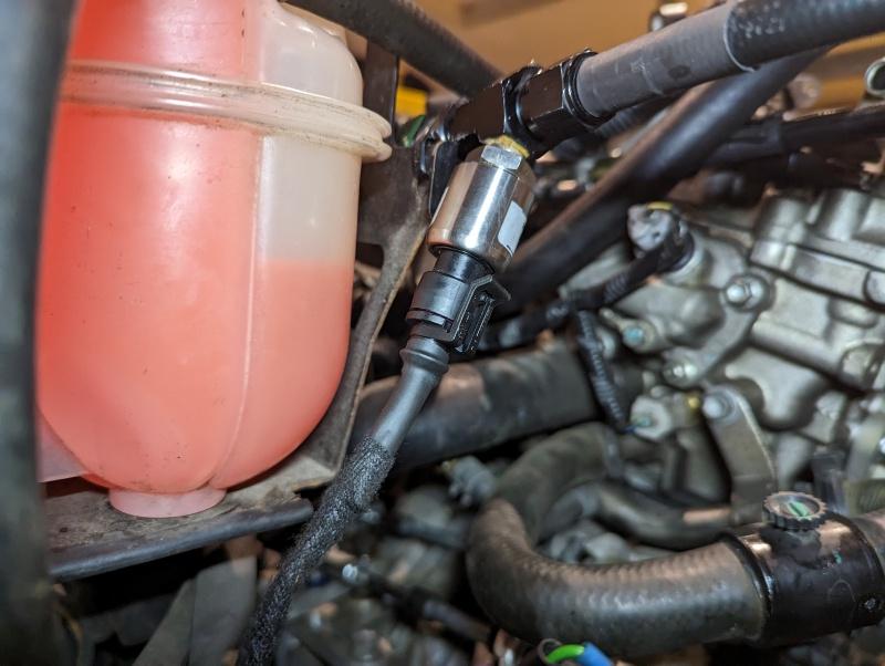
In effect I chopped the four wires, and added a 4 pin DTM connector. This would allow me to re-join it to the factory wiring from the wheel arch if needed, without any tools or recrimping. An additional male connector was then added to the four wires leading to my ADU.

A simple and tidy splice hidden by heatshrink would have been the way any other installer would do it, but I feel this way gives me a perfect rollback.

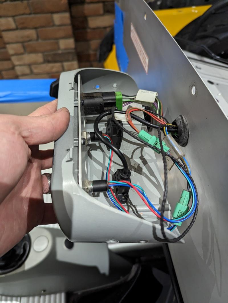
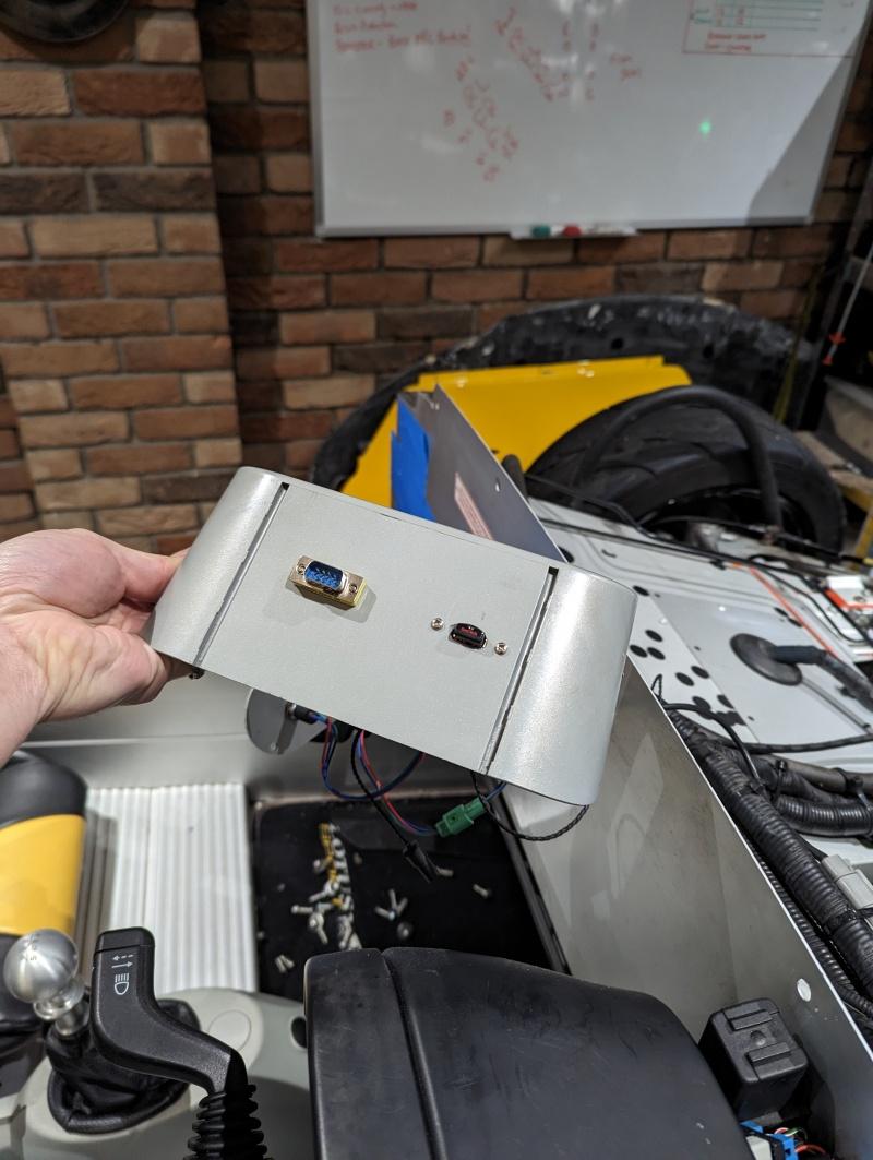
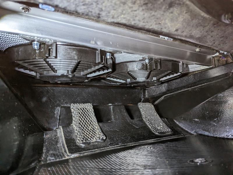
With that done and tested, I moved onto some other ADU housekeeping. The ADU writes its logs to external USB and previously I had this wound up and stuffed into a random panel gap somewhere out of the way, but wanted a neater install. Same for the D9 serial connector for the USB2CAN module.

I’d be sacrificing (drilling and cutting) pretty much the only interior component which is common across the Elise/Exige range (and hence easy to replace if returning to stock) and ran the wiring to this, with the USB stick and D9 port sticking out, out of eye line just below the unit.

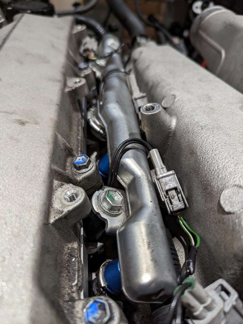
Continuing my theme of butchering the original car as little as possible, I next came up with a wiring plan which would eliminate any splices or cuts into the original engine bay wiring.

The ECU was already PnP so the bulk of it was taken car of by the stock connectors, but pins that are empty on the OE Lotus application are used by the EMU for the wideband lambda and the EDL data logger, so pins were added for those.

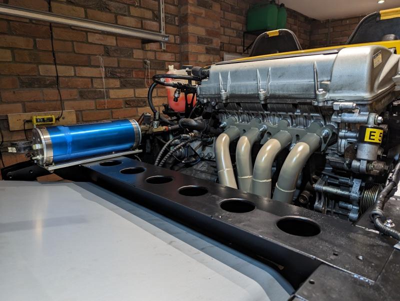
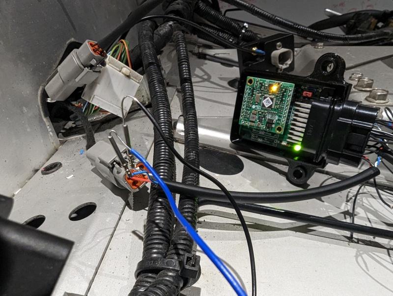
For various requirements I needed ready access to +5v, +12v and grounds. Obviously picking up a random earth point covers one of those things, but for the +5 and +12 I ran a trunk of wires all the way back from the ADU. As the ADU was a custom home made adapter harness, I could cut and splice into that to my hearts content. Running back through the gear lever tunnel to the rear bulkhead I had all of my analogue inputs (for various sensors), +5 and +12v. From there it split off to the various parts of the engine bay.

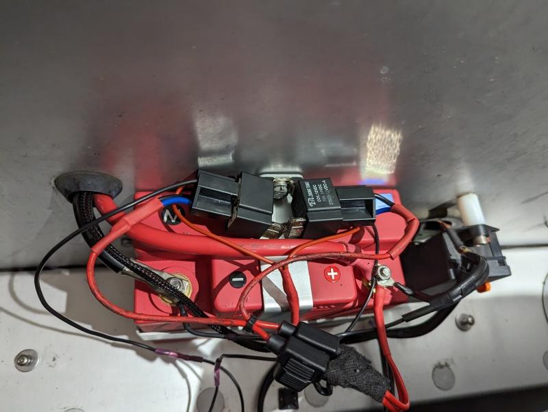
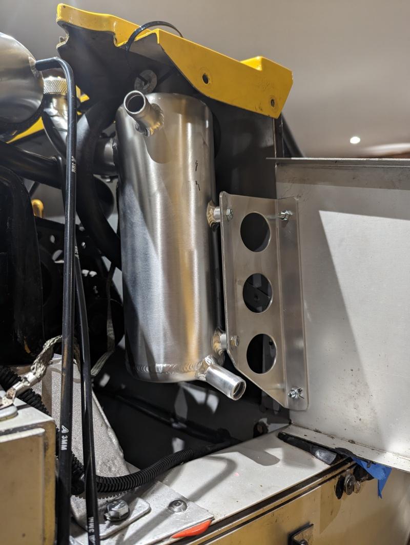
Also in this trunk were the two switch to ground outputs that the ADU provides. These are controlled by software and are connected up to a pair of relays that I’ve mounted in the battery box.

(needs tidying up, I know I know)

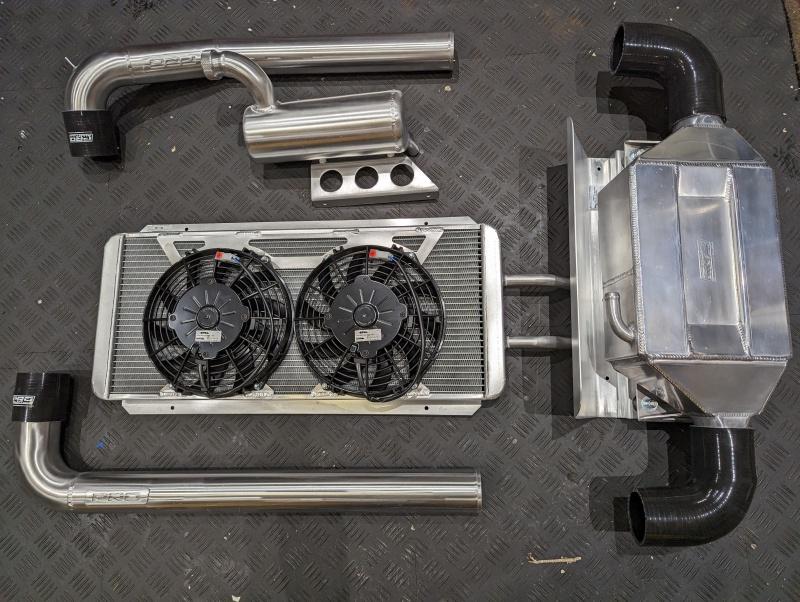
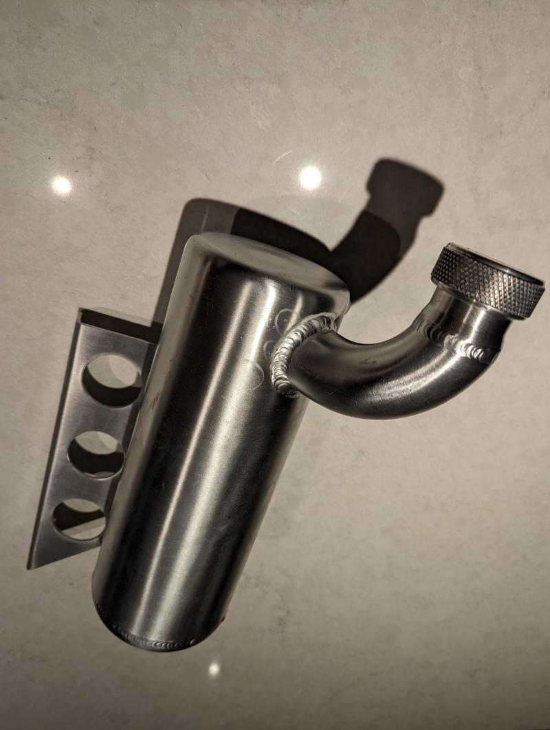
These relays will power the chargecooler pump, and the gearbox oil cooler pump (more on this later). Software in the ADU controls when these kick in, the CC pump will be running pretty much whenever the ignition is live and the gearbox oil cooler will be when the gearbox oil sensor reports a certain threshold.

From the battery box and relays, a small sub harness will go off into the engine bay to the two pumps.

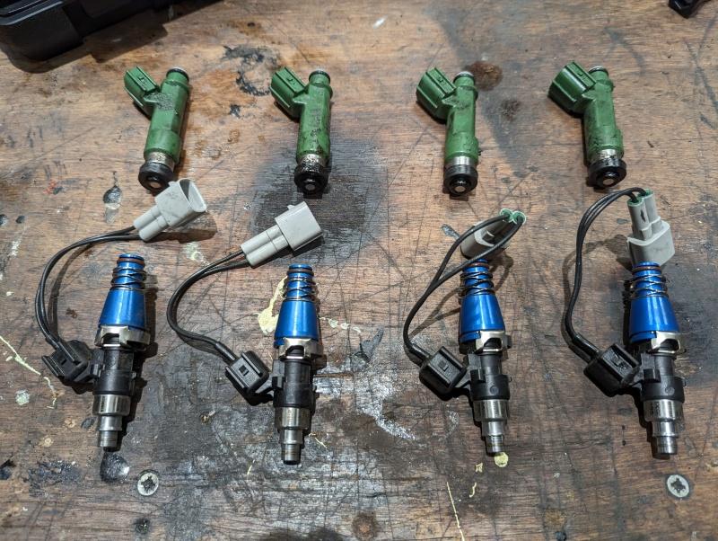
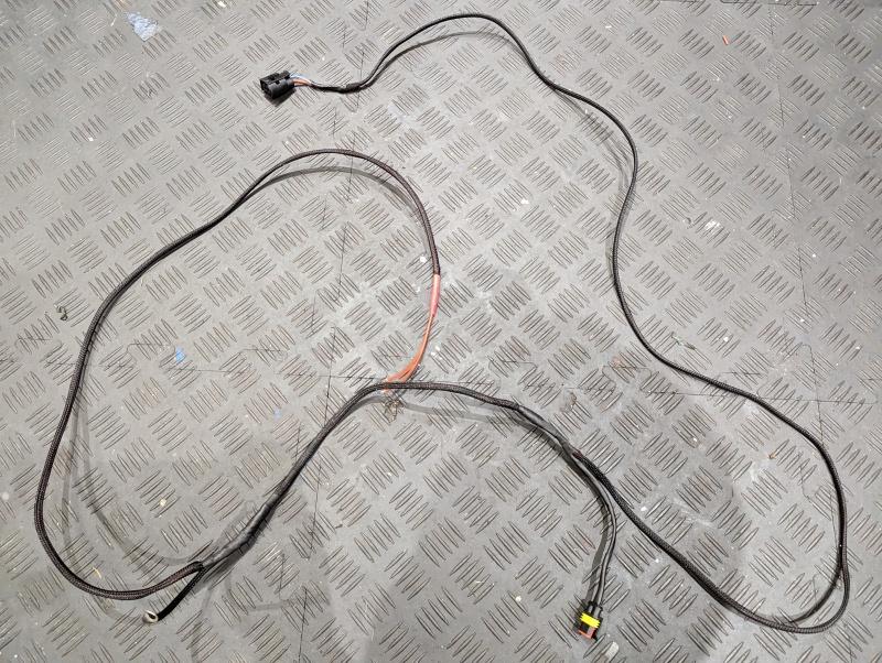
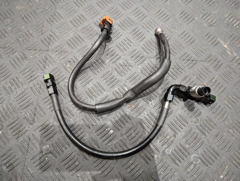
Back to the ECU, I added two pins for the wideband adapter. These add to the four narrowband pins in the OE loom via this adapter harness, made and sold by RRR Engineering:

As readers of my Exige thread will know, I was plagued by lambda sensor failures on my previous EMU install. Since ‘retiring’ the ECUMaster kit on my Exige, the fault was finally acknowledged and a wiring fix was proposed that would add a trace amount of voltage to the WBO VS wire via a 150k resistor. By all accounts, this drastically improves sensor life so I modified the adaptor harness accordingly and added a resistor in to a +5v taken from my “ADU trunk”.

Another issue I had with the EMU on my Exige has also been resolved via a software update. Most (all?) OEM’s have redundant potentiometers for their DBW sensors at both the pedal and the TB. If those readings don’t agree with each other (known as a plausibility check), the car throws a DBW fault code and (probably) goes into limp mode. Clearly a very important safety feature for DBW cars.

The EMU supports all of that, but it was missing the potentiometer correlation options within software to match the Toyota/Lotus setup. This meant that the secondary potentiometer from the TB was being ignored by the EMU for my car (despite being an active wired in input), and any other Toyota/Lotus car out there.

I’m happy to report though that I raised this as a feature request, sent logs over of my potentiometer voltages and their relationships and within 10 days ECUMaster uploaded a new firmware version for this check.

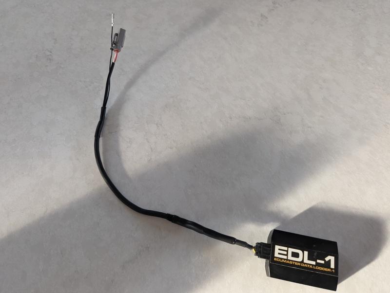
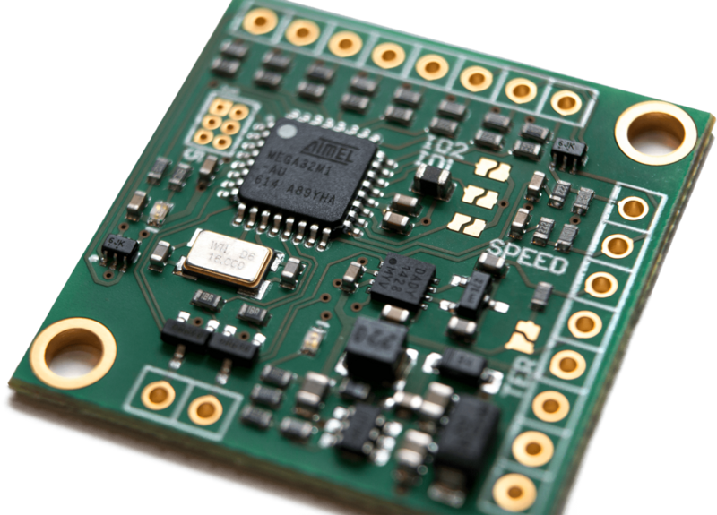
Onto the EDL logger, it has four pins with only three of them actively used (fourth added for a possible future featureset).

+5v (again taken from my ADU trunk)
Ground
Transmit (redundant, for now but pinned into the Receive pin on the ECU)
Receive (pinned into the Transmit pin on the ECU)

The RX and TX pins on the ECU were unused on the Lotus install, so this was just a case of pinning them into empty ports. These can be left in place if the car is ever returned to standard or depinned. Whatever.

I added a 2pin DTM connector to get my power and ground from the ADU trunk.

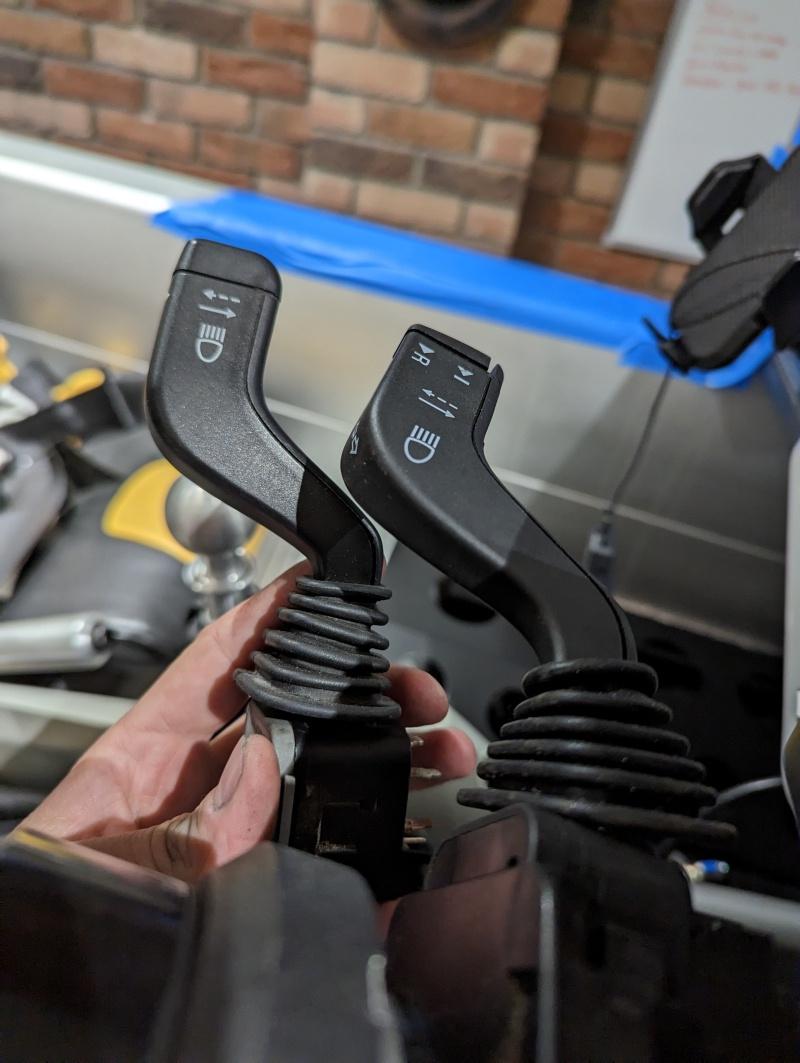
The 2-Eleven has a rotary dial for TC level in the OE wiring. This didn’t require any hardware changes at all to work with the EMU, just a quick scaling of the voltage table for it. The EMU treats the first ‘click’ of the dial as the TC-Off position, whereas Lotus used a dedicated toggle switch. I’ll be recycling that toggleswitch as my map switching button.

Aside from the physical wiring, I did a heap of software stuff to rejig the CAN stream and get the ADU displaying the wealth of data from the ECU. There wasn’t much left after that than to get the actual ECUs swapped out.

I’m very happy with the install, just aesthetically it looks loads better than how my Exige was wired in without little spindly 22awg wires reaching across between the two ECU plugs etc. I acknowledge that my approach of running a trunk from the ADU, and adding DTM connectors everywhere has added weight and complexity but I’m also very happy that by undoing a couple of plugs, swapping the lambda sensor and induction kit is all there is between standard and modified.

Time for first power up, no engine running yet because bits of my engine are still scattered all over the garage! Couple of tweaks to tidy up the config and display setting, but I had all the basics covered. Oil Temp is showing -60ish because it was unplugged at time of filming.

Page scrolling is done by the old trip reset button, ‘race mode’ is my map switching which currently just changes throttle mappings - might do more later depending on the dyno experiments. Plan to run a map close to OE power, and one which is unleashed. I have some more buttons that I’ve not got a use for yet, but I’ll come onto those in a future post if I can think of something.

As for the actual mapping, it’s provisionally booked and as I may have mentioned earlier the plan is to run two maps. One will be close to OE power output in an attempt to preserve the gearbox, the ‘race mode’ will be uncapped on whatever it makes. Not sure yet whether we’ll be using purely throttle mappings to achieve this, ignition maps or a combination of the two. We’ll see how it responds on the dyno.

Bit of work to do before then though :slight_smile:

Oh, brief mention on sensors.

Wideband Lambda wired into ECU and plumbed into the manifold
Oil Temp taken from sump, wired into ADU and passed back to ECU via CAN
Oil Pressure taken from OE sensor location, wired into ADU and passed back to ECU via CAN
Gearbox Oil Temp taken from gearbox secondary fill plug, wired into ADU and passed back to ECU via CAN
Fuel Pressure taken from a replacement fuel rail pipe, wired into ADU and you guessed it… passed back to the ECU via CAN.

1 Like

You just keep on raising the game @Fonzey

You are living in 2033 not 2023

2 Likes

Phew! And I’m worried cos I have a bulb out on the RS!

1 Like

Amazing work and such a tidy install :+1:

I must admit that I didn’t understand most of it, but I enjoyed reading it!

1 Like

[1/2] Last bit of wiring finished over the last few days, so nice to see that all coming together.

Previous post covered getting the sensor wiring back to the engine bay from the ADU, and made a few passing references to the CANBUS expansion plans I had. The ECUMaster ecosystem has a fair few CAN gadgets available, but the best thing about CAN is you can use just about anything from any vendor - as it’s all the same protocol.

My ADU previously had the ECUMaster GPS2CAN unit so I already had the required wiring for that. It’s pretty simple, every device just needs +12v, GND, CAN High and CAN Low. I’d be retaining the GPS module, but also wanted to add TPMS and an ECUMaster CAN switchboard.

The Switchboard would allow me to add a bunch more switches, analogue or digital inputs to the car - and transmit them via CAN. As both my ECU and ADU are at max capacity, the CSB gives me some headroom to expand.

The CSB arrives like this. It’s designed for you to stick in your own projects and does not stand alone as it’s own product as such.

Most often these are used for steering wheel button setups as it’s tiny, can sit on the back of a wheel and then you just need the four aforementioned CAN wires to go back to the dash via one of those curly cord things.

Some time ago, way back when I was working on the Exige I bought a CSB through a company that had made a little 3D printed enclosure for them with a decent plug and some added functionality. Made by RKDE, I can pass on details if anyone is interested.

It came provided with all the pins and bits needed to wire it in, and had a pretty nifty feature in which every pin was duplicated with a ‘linked’ pin, allowing this unit to daisy chain on to subsequent CAN devices.

Something else I’d been sat on for years was a cruise control stalk from GM which the later Exiges used. They’re an exact replacement for the standard stalk, just have a small pigtail for the 3 extra buttons and shared GND.

Using the extra I/O from the CSB would allow me to use these three buttons for whatever ECU or ADU functionality I can come up with.

My CANBUS daisy chain would go from the ADU, to the CSB, to the GPS2CAN module and then finally onto the TPMS module from Haltech.

The TPMS to CAN unit seems to be ripped off and rebranded by a load of companies, they’re all the same under the skin. I chose Haltech because their availability in the UK just made them cheaper, most others are US imports. It comes in two flavours, one with internal sensors that are part of the valve and the other are external valve caps with replaceable batteries.

I spoke to a Haltech rep at the Autosport show and he strongly advised I go for the external valve caps as the integrated ones are single use, and he inferred that they can suffer from connectivity issues. The Haltech ecosystem is brilliantly plug and play, no customer config needed - just ticking boxes and selecting from drop down menus, which means certain things like the CAN Stream message format isn’t documented. The kind chap from Autosport e-mailed it over though, which allowed me to complete the config in the dash.

It sends pressure, temp and alarm data (air leak, battery life, sensor state, etc).

With all my bits collected, time to get crimping.

Taking into consideration the physical IO left on the CSB, and the number of free CAN channels on my ECU left to use - I figured out I could feasibly make use of 2 extra switches (on top of the new stalk) and 4 extra analogue inputs, and at that point - I should really start considering a bigger ECU. With that in mind, I’ve wired in another 8 pin DTM plug which carries those 2 switch and 4 analogue input signals along with +5v and SGND which I can keep cable tied away somewhere for future expansion.

(thinking brake pedal switch for video overlay and maybe even brake pressure sensors for the future)

With my CAN-Daisy-BUS just about finished, it was time to get testing. I had a hurdle to get over which is the CAN speed that the CSB shipped with. Everything on my bus uses 1000kbps, but the CSB shipped set to 500kbps. It’s switchable in software, but if you get a speed mismatch on your CAN network everything seems to crap itself and you can’t configure anything.

With that, I had to setup a bit of a bodge rig to get my CSB power, and grab the CANH/CANL wires to connect to a USB cable and then eventually to the laptop so I could switch the speed. Total bodge, but did the job.

I’d love to say it all sprung to life, but it didn’t. I was seeing data from the TPMS module but my dash display was not showing it. I spent some time second guessing my ADU config but eventually thought to try a replacement battery in one of the valve caps… Doh, they had been sat on a shelf for so long, all four were dead! 4 new batteries later and I had TPMS. Woo!

Made a video: https://www.youtube.com/watch?v=V6vf7ZGSzSc&ab_channel=FonzeyOnTrack

The button I used to use for page changing was the OE trip reset button. A single push would switch pages forward (couldn’t go back, had to loop around), holding it would identify a new start/finish line if racing at a track not stored in the ADU database and pressing it whilst an alarm was active would cancel the alarm - so it was pretty multi function. I still have this setup for everything minus the page switching.

Really happy with how it all came out, need to mount the CAN goodies under the front clam, will be tucked away enough to be weather proof but still in arms reach from the wheel arch for any future changes or expansion.

1 Like

[2/2] Getting a bit out of sequence now and need to get some updates rolled out to stop me forgetting what I’ve done.

Somewhere between all of the wiring stuff, I decided to make a start on the chargecooler and get some stuff off of my garage floor. I couldn’t mount the rear yet, still working with Pro Alloy on a custom bracket for it - but I could get the rad and fans all mounted up.

First up, drained the coolant. Made a massive mess, business as usual.

The radiator shroud comes off the crash structure with just the removal of 6 bolts, and unclipping of some wiring harness. So much easier than the Exige which had AC plumbing to contend with.

Honestly, AC in my Exige was ace - really was effective, and glorious on cooldown laps or road mileage… but it makes working on these cars 10x more awkward for many jobs. I’m loving the 2-Eleven from this perspective.

With the radiator shroud lifted off, I could clean out the crash structure a bit.

Radiator shroud and rad.

The rads are a weakpoint on pretty much the entire Elise/Exige range due to plastic endcaps. Luckily this one has been changed, so one job I do not need to do. The fans would be going in the bin though, Pro Alloy kit came with some nice new ones.

Rad cleaned up nicely after some foam cleaner and a blast with the pressure washer. Just a few bolts to connect the CC pre-rad up to it.

The only real challenge of this part of the install is cutting the holes in the radiator shroud for the pre-rad pipes to go through. I made up a card template which did the job nicely.

Then the fan wiring needs lopping off and the connectors borrowing from the originals.

(solderless heatshrink tubes in the background are my new favourite thing for this slightly chunkier wiring)

Then just a case of bolting the shroud back on, connecting the fans and hoses.

The Actual CC hosing I won’t be running for a bit yet. Need to offer the side panel back to the car and figure out the best route.

Also took the opportunity to mount the header tank to the bulkhead.

Pretty nice position, the pipe neck things actually seem better thought out than the Exige versions and if the side panel sits where I think it sits, there should be a nice tidy hose run which will be barely visible with the bodywork on the car. The goose neck filler might make it awkward to know what my coolant level is, perhaps a sight glass would have been a nice addition but I’ll figure something out.

I have the pump already wired in and tested, so all I can do now is wait for the Pro Alloy bracket to materialise, get the core mounted and then think about plumbing. Oh, and I need to get the sharpie off that header tank.

:+1::+1::+1:Great

1 Like

Have you any idea of the volume of the 2-11 chargecooler resi compared to the exige one?

Looks same, +/- 100ml at most.

If those TPMS sensors are what I think they are, they can be a bit of a liability unless you’re really careful.
The external ones open the schrader valve in the original tyre valve. It then relies on the seal of the new cap to keep the air in the tyre. In the past have seen them leak past the threads, same as a slow puncture; go brittle and break off resulting in almost instant deflation: hit against a curb - road curb when parking rather than a track one - resulting in instant deflation; parked up after a session with the valve at the top of the tyre and over heating the plastic housing, resulting in instant deflation; impossible to set tyre pressure as valve spring is always compressed with the cap on and won’t seat properly when cap removed. And they’re fugly!!
Unless things have changed a bit in the last few years, you can probably tell I’m not a huge fan.
Liking the rest of the goodies though!