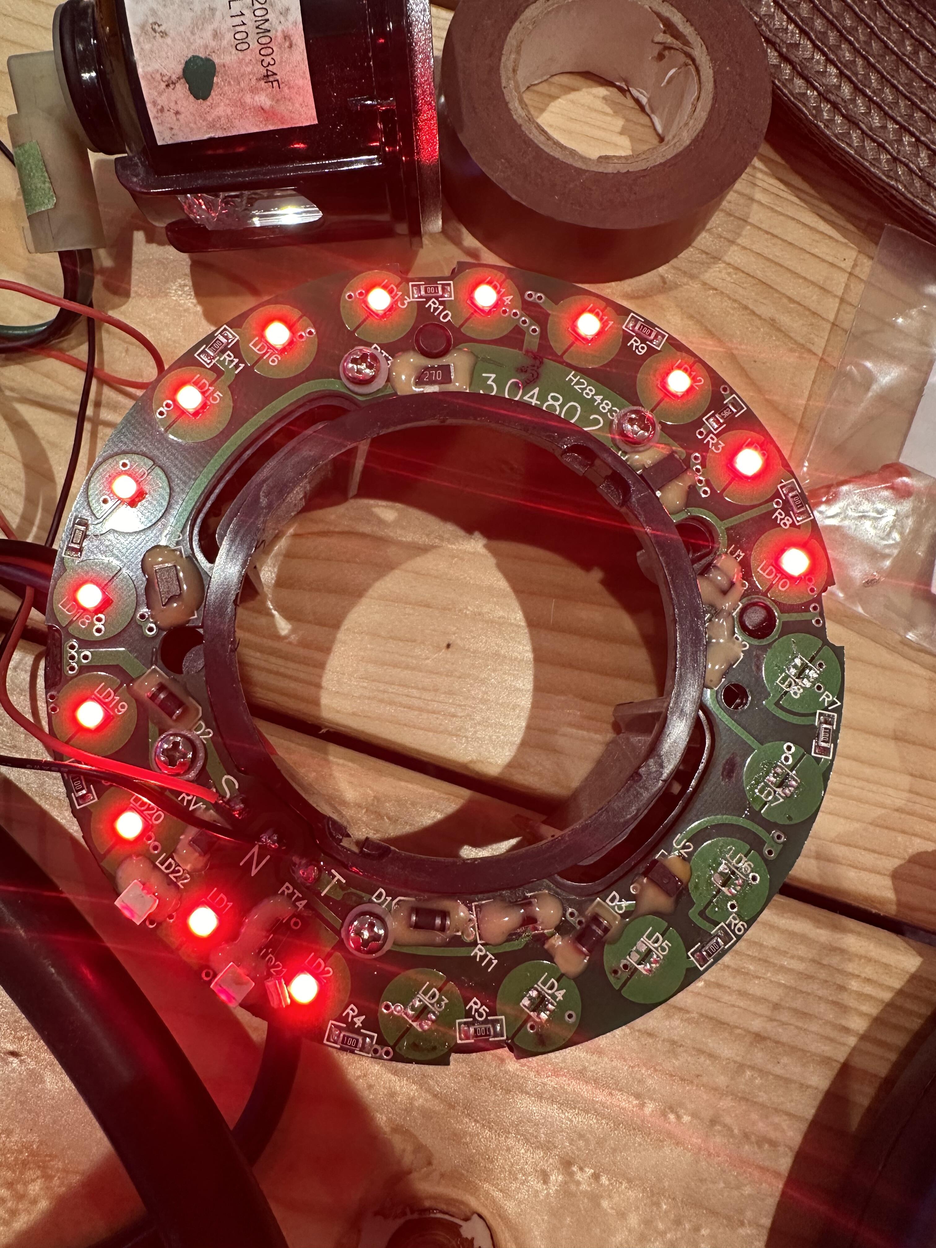
I’ve disassembled one of my tail light in the hope of replacing the leds.
Firstly I’ve de soldered the leds that were either out or very dim.
Before replacing I’ve made a note of the diagram on the pcb. Which seems to indicate 3 anode and one cathod which I’ve tested with a multimeter and don’t get any voltage. I do across a working led.
What I have notice is there is continuity between each side of the pad top to bottom
If you look at ld5 the left pad has continuity top to bottom as does the left, which is confusing me since the diagram and led show only one cathod
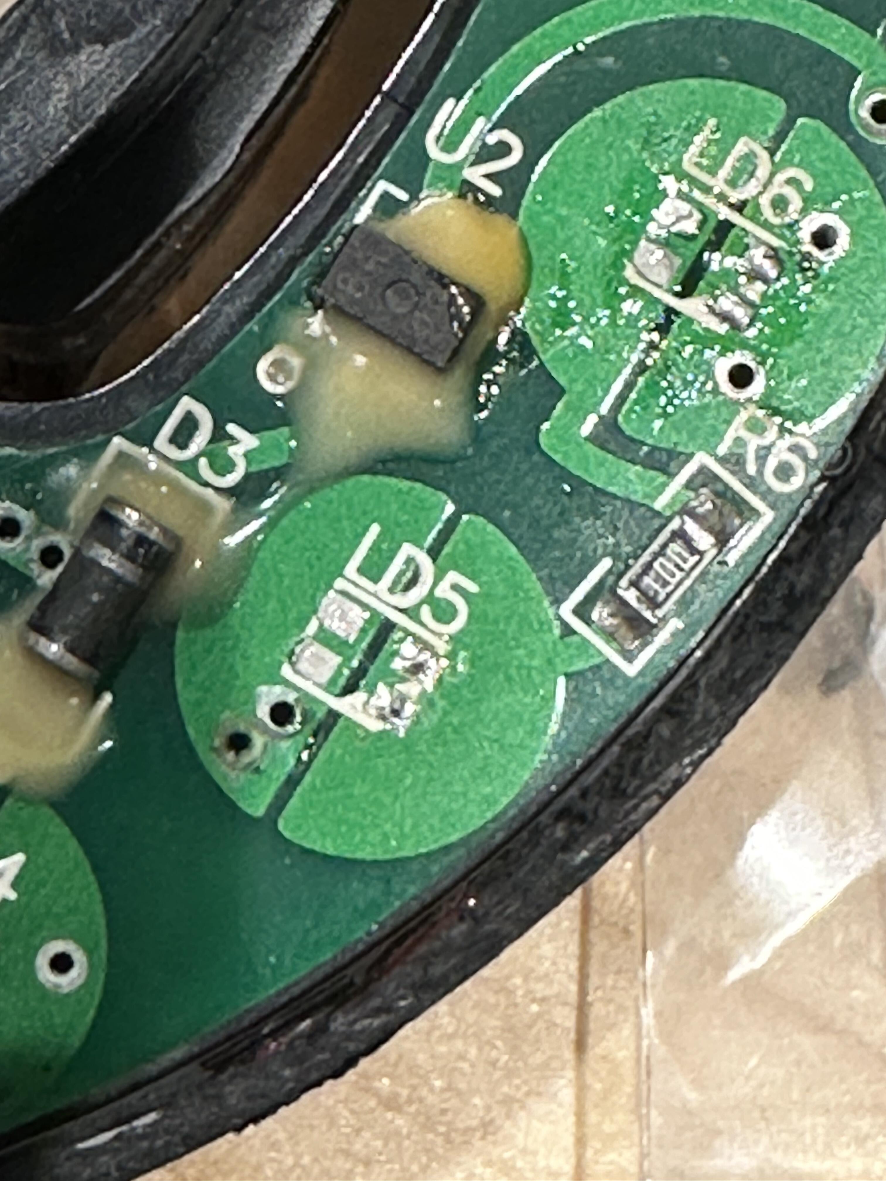
Has anyone any suggestions as to the possible cause. It’s a pretty basic board.