WANTED - Exige S1 177bhp ECM
Anyone got a spare, or one tucked away after an Emerald upgrade?
Thank you Alec.
WANTED - Exige S1 177bhp ECM
Anyone got a spare, or one tucked away after an Emerald upgrade?
Thank you Alec.
Good Morning Alec - How are you ? I may have , its an ebay special I know it works . It doesnt have any felt tip on it so guessing it may be untouched. When you say want , do mean borrow or buy ? I work in Basingstoke .(lucky me )
Yours Dave
Hi Dave,
Thank you for your reply. I’m good, hope your also well.
Although I initially just want to try it to confirm my ECM is faulty, I think it best if I purchase it just in case of accidents, assuming it’s up for sale.
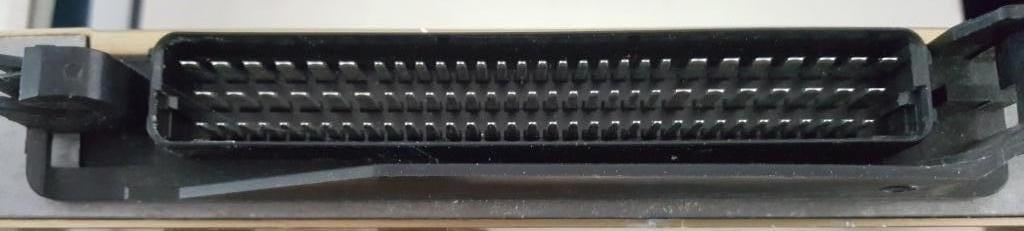
Just to confirm that it is the correct one, I have included a picture of the connector on top of my ECM.
Kind regards.
Alec.
By the lack of response I guess you don’t have the right ECM?
Hi Alec - Many apologies , i had a huge distraction , now resolved and also this site has been messing about with password and I couldn’t respond - so im trying agaiin . thanks for the photo i will check the pins - i have a 190 from my car so it will be an interesting comparison - i would have thought the hardware would have been the same . I am in Horsham sussex this weekend . Please give me a ring and we can make a plan ., As it stands i dont want to sell it - but your more than welcome to borrow for a set time 07526 847978. - yours Dave
If this hasn’t been resolved yet - i have one that i’m willing to sell.
Hi , thank you , Alec borrowed mine and his S1 wouldnt start . I borrowed his and put it in my S1 and ir fired up stright away . Conclusion , Alecs ECU is fine and is not the reason why his S1 wil not start. Cheers Dave
Oh wow and big welcome - just seen its your first post !
Hi Dave, One_PeeJay.
Dave, thanks for replying to this topic, and apologies to One_PeeJay, I thought I had replied. I’ll blame it on old age and too many cold teas.
If you still have a working ECU and have a price in mind why not place it in the parts for sale category.
Or private message (pm) me the particulars, I may be interested if the price is right to buy it as a spare.
PS. Dave the S1 is still refusing to play fair, I showed it pictures of the breakers yard but that didn’t work so to plan C, I bought a Lotus scan 3 tool without the user manual (currently looking for a copy) to coax it into action.
I still have 21 months or so to go until the Exige S1 25th anniversary.
Hope you and your S1 are looking forward to the summer.
Alec.
Hi Alec , Apologies for late reply and happy easter bunnies .
Real sorry to hear this .apart from getting a real modern lotis scan tool on it i dont know what to suggest . I do know its possible as we discussed - Exigence Automotive fixed mine 2022 and identified the reason for not starting was a corroroded wire in the multiblock behind the hand brake on the bulkhead … Stopped the fuel pump energising . Alas Orleans in France is too far to go. But they used modern proprietry lotus scan tool & it was a proper fix .
https://www.exigenceautomotive.com/ - might be worth asking them what sw version they were using ? Just mention EXG 932. Lemans 2022. .
Did we talk about https://www.motorcyclewiring.co.uk/ Ferret ? [07765 832420](tel:07765 832420) He gets susch great reviews on motorcycle loams , customer builds , might be worth phoing him up and see if he could come down and see you , or could recommend someone ?
Always welcome to borrow ECU again if you find an issue and want to recheck . To answer Peejay , I dont want to sell it . To make it worth while its £500 , for that price you can buy an Emerald . so its really not worth it . Id rather loan it out , as once its sold , its really gone from this community . I cant see anyone else taking the risk to loan it. We know it really works and thats a priceless bench mark .
Best of Luck Sire please stay in touch - wishing loads of moral support ![]()
Lotus Exige Wiring Harness Build: Expert Treatment for an Endurance Racer | Top Gear Handcrafted - YouTube ? worth a phone call ?
Hi Dave,
Sorry for the delay in replying to your post.
I checked the multi-block connector behind the hand brake which shows no sign of a fault.
A few weeks ago I purchased a Lotus Tech III scan tool kit, which is a bit limited in its testing capacity when the engine is not running. However it did not indicate any DTC codes stored or waiting on the ECU and information from the sensors it could read seemed ok and nothing out of the ordinary. It does have some rather novel abbreviations which beggar’s belief and prompted me to look for the manual sadly missing from the kit.
All the ECU input sensors, the 48 pin bulkhead connector and the ECU 88 pin connector wiring are good, all tested for continuity and signal with an oscilloscope where applicable. I could not find anything wrong, except a strange change in the Crankshaft Position Sensor signal after the 47K ohm resistor, which I have just emailed Lotus for some help with. I’ll include some pictures to illustrate this.
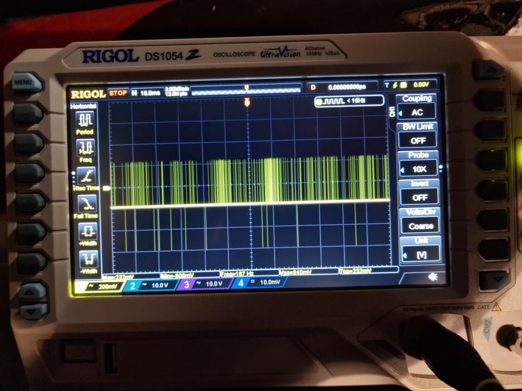
My knowledge of resistance in an AC circuit is limited to Marine Engineering where resistors are commonly used to align voltage and current in AC capacitance circuits. But this resistor seems to reduce the CPS signal from 5.4Vpp to 0.8Vpp a signal so low I’m not sure the ECU will read it. Could this be the problem?
Your offer to loan the ECU again will be gratefully accepted, may I contact you a little later on to arrange a loan if Lotus fob me off with the usual seek your local dealers assistance.
Thank you for your ECU loan offer and moral support.
What is the actual issue with your Exige?
Are there any non factory parts fitted? Flywheel in particular? MAP and BARO sensor connected the correct way around? Good fuel pressure? IACV bracket still in one piece?
Hi JDS,
The issue is the Exige fails to start.
Yes there are some non-factory parts fitted, all of which have been procured from respected lotus spares suppliers. These include DeRoure, Bell & Colvill, Southwest lotus centre, eliseparts, elise-shop, Rimmer brothers and Holden Vintage & Classic. Some non-strategic parts such as fixing hardware, heat and sound proofing have been purchased from various on line sellers.
The flywheel along with the clutch, pressure plate and bearing came as an Exedy clutch and flywheel kit from Eliseparts. I have contacted Eliseparts to ask them about Exedy clutch & flywheel kit and received the following reply from the MD back in June last year
“we have sold in well over 500 flywheels in the past 10 +years and the only issue we have had was with the VHPD engine I mentioned. It did have an Emerald and it was something to do with the signal settings within the ECU (from memory as it was several years ago)”
The ECU on my Exige is as factory fitted, and been tested by placing it in another Exige and firing the engine up successfully without issue.
The MAP and BARO sensors are connected as per the wiring diagram, 16254539 (MAP sensor) has the black connector and 16006835 (BARO sensor) has the Blue connector.
I have not taken a fuel pressure reading, although I know the pump works as it pumped 14 litres of old fuel out of the fuel tank before pouring 12 litres of fresh fuel back into the fuel tank. Lines have been flushed through and a new filter fitted.
The I.A.C.V bracket failed and I replaced it with a pipe bracket to secure it in the right location.
Using the Lotus Scan III tool, no DTC codes are present or pending.
My initial investigation diagnosed a failure of the fuel injectors and ignition coil pack to operate.
The fuel injectors are not operating because the Fuel/injector relay is not being activated. The relay works as it turns the fuel pump on for a few seconds when the ignition is turned on. The fuel/injector relay coil is energised from terminal 53 on the ECU.
The coil pack is not sending the high voltage to the spark plugs since it too is not receiving signals from terminals 29 and 49 of the ECU.
Since testing for signals at the ECU connector (pins 53, 49 & 29) proved fruitless and the ECU works, I concluded that it was an input to the ECU that was preventing the ECU sending the required voltages/grounds.
The only sensor with input to the ECU during cranking I can see, which would cause both these issues is the Crankshaft Position Sensor. Which is why I have focused my attention to this system.
Assuming that the Exedy flywheel is both the correct version (13, 3, 14, 2) and fitted correctly (from memory a location dowel in the crankshaft prevents incorrect fitting of the flywheel, so negating the possibility of a timing issue) and the ECU is fully functional. The system failure candidates are, Reluctor ring, CPS, CPS connector, wiring, bulkhead 48 pin connector, ECU connector or the 47K ohm resistor.
Changing the CPS did not change anything. The original 22 year old CPS was still capable of generating a 5.2Vpp voltage.
As per my last post, the new CPS generates a 5.4Vpp signal during engine cranking, this can be measured at the CPS sensor and between terminal 79 of the ECU connector and the sensor side of the 47K ohm resistor. This would suggest that the Reluctor ring, CPS, CPS connector, wiring to pin 79 of the ECU connector (black wire), bulkhead 48 pin connector, and wiring up to the 47K ohm resistor (white wire) are functional.
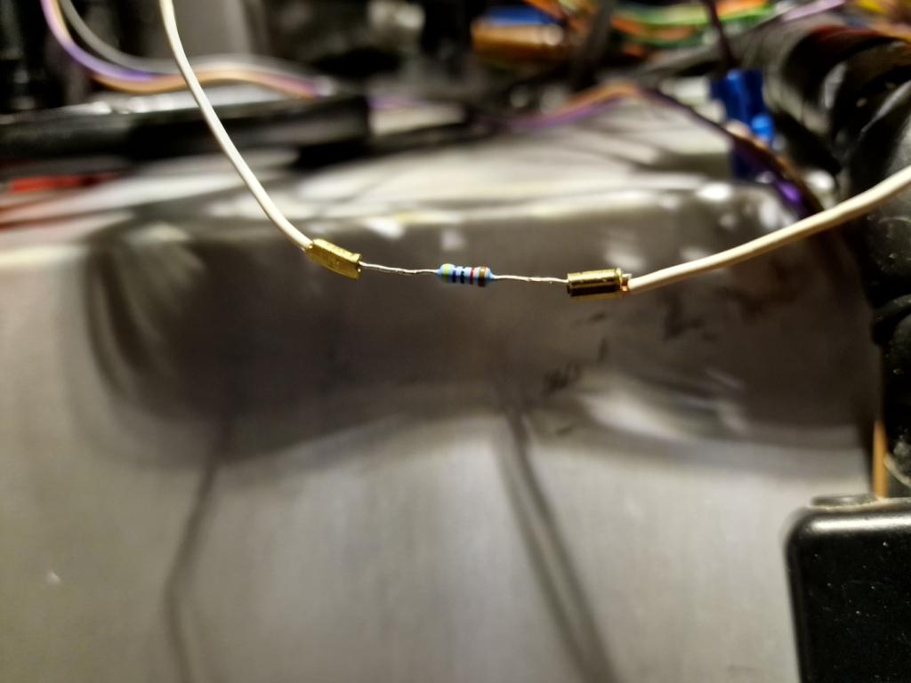
The resistor measured in circuit is 47K ohm resistance (as per the wiring diagram) it would seem to be correct, although the 50mm wire length between the resistor and ECU connector is more like 200mm in practice.
The last focus of investigation is between the ECU side of the 47K ohm resistor, ECU pin 73 and ECU pin 79, where I measure a voltage of 0.84Vpp. Without knowing the ECU specifications I don’t know if that voltage meets the ECU expectations or is too low for the ECU to read/respond too.
In conclusion, if the ECU is expecting a larger voltage than 0.84Vpp, I have two options open to me. The first is to close the air gap between the CPS and the reluctor ring. The current air gap is approximately 1.1mm, not a lot of potential gain here. Or change the 47K ohm resistor for a smaller one, not something I wish to consider.
Or have I missed something and been barking up the wrong tree?
I’m a little curious about the broken I.A.C.V bracket issue you raised, what is the significance?
Thanks for your interest.
You have been through pretty much everything. I’m not sure that .8V is a problem, it depends on how the ecu circuit is designed.
As the ecu does not use a cam sensor it uses a missing or extra tooth on the crank to determine TDC and then runs wasted spark and fuel on the induction an expansion strokes. If it can’t detect tdc it will not fuel or spark.
I have no idea how it could fail to detect the tdc and I think I can see it on your scope trace. Just an idea, good luck.
It sounds like you have done most of the normal checks.
When did the engine decide to not start? Anything changed just before it failed? When you say the coils and injectors don’t fire, are they not getting a positive feed or an earth trigger from the ECU?
The relavence of the IACV bracket is that when they break, the valve hangs around on the hoses, but they are flexible enough for the wiring connector/wires to hit the gearbox on right hand turns, eventually chaffing through the insulation and blowing the fuse on the bulkhead by the ECU. This fuse also feeds the ECU at pin 8 and shuts the engine down.
We have also seen one Exige that didn’t like the EP flywheel. As there is only one set of trigger teeth , rather than two on the standard flywheel, it would start and rev, but only to about 4k, then loose engine speed signal, cut fuel/spark, the revs would drop, regain speed signal and rev again to about 4k, and repeat. We did the same as you, new sensor, just the same. In the end, we were moving the crank sensor around without the bolt in, while being reved, and in some positions it would work fine others the ‘rev limit’ would get even less. In the end, we managed to very carefully machine a small amount off the landing face of the sensor so that it went in further, and it’s been fine since. If you try the moving the sensor while running thing, ensure that the closing panel on the gearbox is fitted!! And be carefull!
I think you said that you have a Lotus OBD tool? You should be able to get to the live data screen and look at engine speed while you are cranking. Just because you are seeing a trace on the scope, it doesn’t mean that the ECU is seeing what it needs to operate coils and injectors.
Hi winthatt,
Thanks for your post.
Yes the engine ignition coil only has two inputs so is a wasted spark system firing on cylinders 1 & 4 and 2 & 3 on both the ignition and exhaust cycles.
Since the ECU voltage expectation from the CPS is not a given in the Lotus Service Notes manual it remains an unknown. 0.84Vpp may or may not be a problem, it’s the only issue I can find and possibly a question only Lotus can answer.
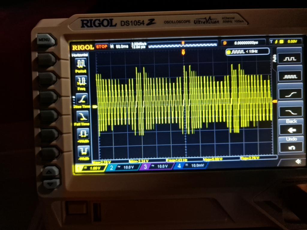
I admit I should of aligned the first scope picture better to illustrate the cycle, however if you read it from right to left (the first 2 spikes are missing from the picture) the cycle is 13 teeth, space (110°btdc), 3 teeth, space (150°btdc), 14 teeth, space (300°btdc), 2 teeth, space (330°btdc).
Each spike is the voltage generated by the tooth passing the CPS, and the space is a missing tooth.
The maths is easy since it has 32 teeth (voltage spikes) and 4 spaces, 360°/36 = a tooth every 10° of rotation.
I cannot be absolutely sure where TDC is in the cycle as the Manual only indicates TDC for standard and VVC not the VHPD engine.
My flywheel reluctor ring configuration seems to be aligned to the VVC engine, as stated in the manual, 110° BTDC, 150° BTDC, 300° BTDC & 330° BTDC. TDC could possibly be the 3rd spike from the left in the first oscilloscope picture?
I thought the scope trace looked ok but I cannot remember the pattern. If you have aligned the sensor incorrectly I’d expect it to fuel and spark but at the wrong time.
I’m out of sensible ideas. One stupid idea is, s1 uses two wheel speed sensors, one for the stack and one for the ecu. My ecu sensor failed and I had all sorts of Rev limit and missfire pops and bangs. I can only assume the WSS is used to set some mode in the ecu software. It’s an easy test, unplug the driver’s side WSS. Really clutching at straws.
JDS may be right, it could be the flywheel teeth shape and alignment. Not easy to try but a stock flywheel may be worth a try.
Hi JDS,
Thanks for your post.
The Exige has been laid up in the garage since 2007, now I have more time and less trust in garages I decided to give it a complete overhaul, so almost every part has been removed inspected reconditioned or replaced during the last 3 years.
It has not been started since it was laid up after discovering damage to the block and head, post a garage visit to replace the head gasket. (Taking a friends garage recommendations is not necessarily the right option.)
As I mentioned in my post, there is no supply from ECU pins 53, 29 or 49 positive or negative during engine cranking. The fuel/injector relay coil, needs a positive supply from pin 53 to make the relay contacts thus providing a path for a positive voltage to the fuel pump and injectors. Since pins 29 & 49 do not supply a signal to the coil, a high voltage is not delivered to the spark plugs. I’m assuming the latter is because a spark is not required if fuel is not present.
No issue with the I.A.C.V, it’s held firmly in position with wiring intact. All fuses are good. Pin number 8 is receiving a 12.04v supply from the 3 amp fuse in fuse box B (rear cockpit bulkhead).
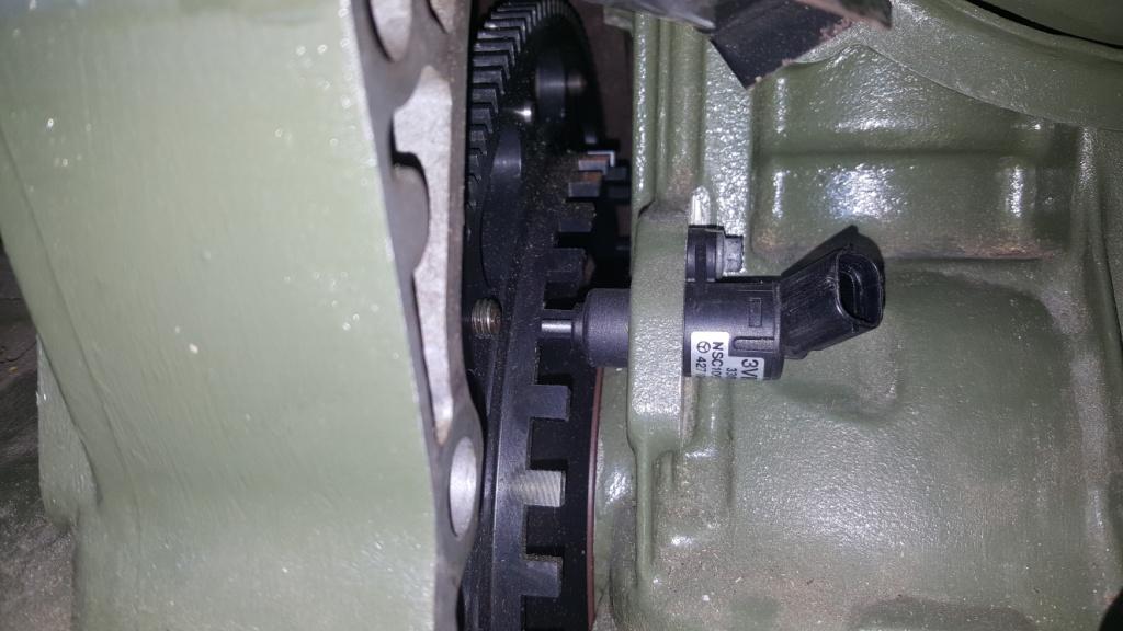
I don’t believe that the CPS position is an issue, I have posted a picture for your comments, and what do you think?
Yes I have the Lotus scan III kit with T0001426F scanner tool. I tried to get a live scan but unfortunately the scanner loses connectivity with the ECU during engine cranking and the live data with the engine static is of limited use. Once again I’m open to suggestions, but suspect that since the battery voltage drops during cranking the communication cannot be maintained. It’s a new Exide battery fully charged so no issue there.
However if you look at the first picture, it’s possible to read the time taken for a complete cycle and calculate the cranking RPM at about 190rpm. A cycle (34 peak signals and 4 spaces) is about 6.25 squares on the first scope picture. As the square represents 50m seconds 0.050, 6.25 * 0.05 = 0.312 seconds per cycle. 60/0.312 = 192rpm.
Your last paragraph is exactly my question, is a 0.84Vpp signal large enough for the ECU to read. This signal not only tells the ECU the position of No 1 cylinder for fuel injection and spark, it also provides the signal informing the ECU of the engine speed for timing adjustment.
Annoying that the comms to the check tools falls over when cranking!
Does your fuel pump prime when you first turn on the ignition?
Pin 53 is a live output to the fuel pump/injector relay, and is earthed via the inertia switch, to the chassis or head. If the fuel pump primes it suggests that the wiring is OK, the ECU is doing what it should and at least the pump contacts in the fuel pump/injector relay is good.
Do you get a corresponding live at the injectors at the same time as the pump is running. If yes, then the other set of contacts in the fuel pump/injector relay is good. It’s best to do this with a test light, with all the injectors disconnected, rather than a multimeter, as a multimeter will show 12 volts, but no idea on the amps.
The coil gets its live feed from another fuse in the bulkhead fuse box - B4 I think, as my copy at home is a little fuzzy - and earthed via the ECU at pins 29 and 49. Do you have an ignition live feed to pin 2 at the coil pack?
If yes to pump primes, live at coil pack and live at injectors while pump is priming, then I’m suspecting the crank sensor/flywheel ring is your issue.
If you look at the picture of the crank sensor, where the mounting bolt is, you can carefully file off the little mounting boss that fits between the engine block and mounting wing moulded onto the sensor. That was enough to sort out our 4k rev limiter. It would be worth making sure the engine turns over without touching the flywheel before cranking over on the key.
Let me know how you get on and I’ll have a bit more of a think in the meantime.